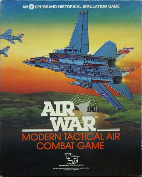
Air War: Modern Tactical Air Combat
Air War: Modern Tactical Air Combat Rulebook
Table of Contents
Table of Contents
- 2.0 General Course of Play
- 3.0 Definition of Terms
- 4.0 Game Equipment
- 4.1 The Game Map
- 4.2 The Playing Pieces
- 4.3 The Aircraft Performance Charts
- 4.4 The Weapons Track of the Aircraft and Missile Control Display
- 4.5 The Movement, Throttle, and Energy Points Track of the Aircraft and Missile Control Display
- 4.6 The Other Tracks of the Aircraft and Missile Control Display
- 4.7 Use of the Altitude Indicator (Altimeter) on the Aircraft and Missile Control Display
- 4.8 Missile Performance Charts
- 5.0 Sequence of Play
- 6.0 Position
- 7.0 Initiative
- 8.0 Flight
- 9.0 Turning
- 10.0 Changing Altitude
- 11.0 Maneuvers
- 102.0 New Maneuvers Commentary
- 12.0 Probability
- 13.0 Cannon Combat
- 14.0 General Missile Combat
- 15.0 Heat-Seeking Missile Combat
- 16.0 Radar-Homing Missile Combat
- 17.0 Loaded Condition
- 18.0 Optional Rules
- 19.0 Visual Search
- 20.0 Radar Search
- 21.0 Pilot Capability
- 22.0 Natural Phenomena
- 23.0 Infra-Red Counter-Measures
- 24.0 Radar Counter-Measures
- 25.0 Bombing and Strafing
- 26.0 Ground Installations
- 27.0 Ejecting
- 28.0 Aircraft Equipment Tables
- 29.0 Playing the Scenarios
- 101.0 Introduction (Air War '80 Addenda)
- 103.0 Advanced Air-to-Ground Rules
- 104.0 Special Aircraft Rules
- 105.0 Aircraft Use
- 106.0 Special Weapons Rules
2.0 General Course of Play
2.1 Complexity
In games in general, there are two types of complexity: conceptual complexity, and mechanical complexity. Chess, for instance, is mechanically simple — the rules are easily explainable, the moves limited and obvious — but conceptually complex — strategies are complex and intricate, moves long-deliberated. Most wargames are the reverse; that is, mechanically complex — they have long rules, intricate procedures, and lengthy explanations — but conceptually simple — the movement of units occurs in a relatively simple manner, combat is resolved according to a rather simple procedure.
Air War, however, is both mechanically and conceptually complex. The rules are extensive, long, intricate and contain new concepts not often utilized in wargames; movement of aircraft occurs only after tremendous thought, manipulation of markers on the Aircraft Control Charts, and execution of procedures.
Therefore, Air War is a very difficult game, both to learn and to play. It is suggested that people purchasing the game would be better off if they have some previous knowledge of wargames or the concepts that go into them. Even then, Players may have some difficulty in learning the game. They should be warned that the first several times [the source text layer ends this sentence here; no further words are present in the source].
However, it is the opinion of those who worked with the game that it is partly Air War's complexity that makes it an interesting game, and that its complexity will ensure that, unlike some other games, Air War will not become boring after a few playings.
2.2 Playing the Game
Air War is played in successive Phases, in which the Players each execute various procedures alternately. During the Initiative Determination Phase of each turn, the Players determine who is to go first throughout that turn; the first player then executes a given Phase before the second Player does, after which they proceed to the next Phase. Note that Initiative determination depends on aircraft position — so if one Player's aircraft have the "jump" on another's, he is more likely to have the initiative.
During the Movement Phases, the Players move their aircraft. Note that there are three separate Movement Phases. In the first, all aircraft that are at a disadvantage are moved; in the second, those that are neither advantaged nor disadvantaged are moved; and in the last, those that have an advantage are moved.
Movement of aircraft occurs according to a complex series of procedures. There are different rules for diving, climbing, turning, executing maneuvers, and so on. The movement rules are in fact so complex that four sections are devoted to various facets of movement.
Two of the basic concepts involved in movement are momentum and facing. Aircraft are forced to expend all of their Movement Points in every turn, unlike some other SPI games. That is to say, aircraft may alter their speed depending on certain conditions, but an aircraft must move as quickly as its current speed would allow it to — no more, no less.
In addition, Air War uses a unique twelve-point facing system; basically, this means that an aircraft may face either towards a hex-side, or towards the juncture between two hex-sides, known as a "hex juncture." This allows aircraft more flexibility in movement than in many other air games.
Combat in Air War occurs either through the use of cannons (air-to-air guns) or missiles — either Heat-Seeking or Radar-Homing. The optional rules add anti-aircraft guns, as well as SAM's and air-to-surface missiles. Missiles in Air War are differentiated as to type; that is to say, an early Sidewinder missile will operate differently from an AA8 Aphid missile, even though both are Heat-Seeking.
2.3 Scenarios
Scenarios are dealt with in two different ways in Air War. Firstly, there are "Historical" scenarios, which present either an actual or a conjectural situation, complete with set-up hexes, weapons available, and special rules to cover the situation. These are analogous to those scenarios provided with other SPI tactical games, such as Patrol!. Included among these are two rather odd scenarios introduced to satiate the developer's sense of whimsy — one in which the Air National Guard is pitted against a dragon, and another in which a flight of F-15's attempts to destroy an intruding flying saucer.
In addition to these scenarios, the Players are provided with a list and description of "scenario types;" that is, general situations that often arise in modern air combat. At the end of the rules are a number of "Availability Charts" which detail aircraft, missiles, ECM devices, and so on which are or may be available to the various nations of the world at varying times.
Using the Availability Charts and the list of scenario types, the Players can easily construct their own scenarios, either pitting aircraft types of their fancy against each other, or specific nations' air forces against each other.
2.4 Game Scale
Each counter in Air War represents an individual aircraft or missile. Each hex represents a space 500 feet in diameter; each level of altitude represents 250 feet. Each Game-Turn represents 2.5 seconds of real time.
At sea level, a Movement Allowance of 5.61 represents a speed of Mach 1 (766 mph).
At 15,000 feet (60 levels of altitude), Mach 1 (722 mph) is equivalent to a Movement Allowance of 5.29.
At 25,000 feet (100 altitude levels), Mach 1 (692 mph) is equivalent to a Movement Allowance of 5.07.
At 35,000 feet (140 levels), Mach 1 (666 mph) is equivalent to a Movement Allowance of 4.88.
At 45,000 feet (180 levels), Mach 1 (659 mph) is equivalent to a Movement Allowance of 4.83.
2.5 Game Parts
Included in a game of Air War should be the following parts:
- 4 individual Map-Sections
- Counter sheet containing 400 counters
- Counter sheet containing 200 counters
- Aircraft and Missile Control Displays
- Game Chart booklet
- Rules booklet
- Plastic Dice
- Game Box/Coversheet assembly
Questions concerning the rules to Air War that are phrased in such a way as to be answerable in a one-word reply will be answered if sent to the address below together with a stamped, self-addressed envelope. Mark inquiries "Air War Question" and address to: Simulations Publications, Inc. 44 East 23rd Street, New York, N.Y. 10010
3.0 Definition of Terms
Much of the terminology used in Air War is not standard usage, as many concepts in Air War are not common to most games. It is suggested that the Players familiarize themselves with these terms:
Advantaged: Basically, an aircraft is said to be "advantaged" when it is facing towards another aircraft, and that aircraft is not facing towards it; an aircraft is considered "advantaged" when an enemy aircraft is in its "forward arc" (see Section 6.0).
Aircraft and Missile Control Displays: The Aircraft and Missile Control Displays are the large sheets provided with Air War; there are four of each. Each Control Display is used to keep track of the various markers that each aircraft uses to represent various facets of its movement (and combat). Note that each Aircraft and Missile Control Display contains enough tracks to provide for the markers for four separate aircraft (or missiles).
Aircraft and Missile Performance Charts: The Aircraft and Missile Performance Charts are bound in a separate booklet. Each Performance Chart bears the tables and charts that contain all the data needed for use of one aircraft type (or missile type); therefore, each aircraft (or missile) has its own Performance Chart, separate and different from all other Performance Charts.
Altitude Level: Altitude is not kept track of directly on the game-map; rather, each aircraft has a set of Altitude markers that are used to keep track of its altitude. Altitude is in terms of altitude levels; one altitude level represents 250 feet, or one-half of a hex.
Altitude Grouping: Various aircraft characteristics change as the altitude at which the aircraft is flying (see the Aircraft Performance Charts). For simplicity, altitude is broken up into four broad groupings: Low (symbol "LO") from level 1 to 60; Medium-Low ("ML") from 61 to 100; Medium-High ("MH"), from 101 to 140; and High ("HI") above 140 altitude levels.
Arcs: The concept of arcs is one that is used often in the Air War rules, both for determining Initiative and for combat. Basically, the hexes around a given aircraft are divided into six different arcs, each arc taking up approximately 60° around the aircraft. For a more complete explanation, see Section 6.0.
Disadvantaged: Basically, an aircraft is considered "disadvantaged" if an enemy aircraft has the advantage over it.
Flight Attitude: Flight Attitude is a term which encompasses two facets of an aircraft's positioning; the position of its wings (i.e., how far the aircraft has rolled, how its wings are banked); and the rate at which it is diving or climbing. An aircraft's flight attitude is kept track of on the Flight Attitude Indicator of the Aircraft Control Chart.
Hex-juncture: A hex juncture is the point formed at the intersection of two hex-sides; note that there are six hex junctures around each hex.
Hex point: Each hex has twelve hex-points; essentially, a hex-point is a direction in which an aircraft may face. Each hex-side and each hex juncture is considered to constitute a hex point.
Loaded Condition: An aircraft is considered to be Loaded when it is carrying so much cargo (or stores or ECM devices) or has been damaged so extensively that its operation is severely affected.
Maneuver: A Maneuver (with a capital "M") is a specific way in which an aircraft may move that contravenes the normal rules of movement. Barrel-rolls and Immelmanns are cases in point.
Movement Allowance and Throttle Setting: An aircraft's Movement Allowance and its Throttle Setting are two independent but inter-related entities. Its Movement Allowance is its current airspeed, the number of Movement Points that it must expend in a single turn (providing that the Movement Allowance can be changed if the aircraft dives, climbs, or executes some kind of Maneuver). Its Throttle Setting is the thrust being applied by the aircraft's engines, and does not change if the aircraft dives or climbs; it may only be changed if the aircraft voluntarily accelerates or decelerates. In level flight, if no outside forces are acting upon an aircraft, its Movement Allowance will be equal to its Throttle Setting.
Probability Number: Under many circumstances, the rules direct the Players to generate a "Probability Number" in some way (usually by referring to a table). This number is the chance out of 36 of some event taking place — the event determined by the circumstances. For instance, when resolving Cannon Combat the Players must determine a firing aircraft's Probability Number of hitting its target. The Players then refer to the rules for Probability and the Probability Table to determine whether the event takes place — in this case, whether the firing aircraft hits its target.
Radar Lock-On: An aircraft is said to have a Radar Lock-On to an enemy aircraft when it has successfully "painted" that enemy aircraft with radar. Radar-Homing missiles home in on radar "paints" obtained by friendly aircraft, and thus an aircraft must obtain a Radar Lock-On before it may launch Radar-Homing missiles.
Tracking Cones: An aircraft's Tracking Cone is a cone which extends from its nose across the game-map. There are two types of Tracking Cones — Normal Tracking Cones, and Limited ones. Normal Tracking Cones are 60° across; the Limited ones are approximately 14° across.
4.0 Game Equipment
4.1 The Game Map
The game-map is a blank map used to represent aircraft positions and movement. A hexagonal grid is superimposed to regularize movement. Although it is referred to as a "map," it bears no terrain — there are, after all, no mountains or forests in the air. However, clouds, the sun, and the height of the land are represented in certain scenarios, according to the optional rules for Natural Phenomena.
The game-map is divided into eight "map sections," each approximately 8½ x 11. They fit together to form a single map which is "geomorphic;" that is to say, individual map sections may be moved from one position to another as aircraft move and as the game progresses, so that it is impossible to fly off the map — as soon as an aircraft comes to the edge of a map section, another section is moved from its previous position to the map edge, so that the aircraft's position can continue to be represented.
On each map-section is a compass rose, indicating the twelve cardinal directions that are used in Air War; this may at first be confusing, but perusal of the rules for Turning should clear the matter up.
4.2 The Playing Pieces
The playing pieces (thereafter "counters" and "markers") are colored, die-cut counters. They are divided into two general groups — counters, which are pieces representing actual aircraft; and markers, which are playing aids used for various functions in the course of the game. The counters are color-coded as to the country of origin of the aircraft represented — thus, American-built aircraft will be one color, Soviet-built aircraft another, and so forth.
There are two general types of markers; those that are used on the Aircraft and Missile Control Display and those that are not. Note that each aircraft counter has an identification number, which is a number between one and eight. The Control Display markers are grouped into two differently colored sets of markers; each set containing eight subsets of markers, each sub-set assigned a number between one and eight. A given aircraft is represented on the Aircraft Control Chart by markers assigned the same subset number as the identification number of the aircraft. It may be necessary, however, to use markers number 5-8 for aircraft numbered 1-4.
4.21 Summary of Unit Types — (The Summary of Unit Types chart is a graphic in the printed rules and is not present in the text layer of this file.)
4.3 The Aircraft Performance Charts
Provided with Air War is a booklet of Aircraft and Missile Performance Charts. This booklet contains all of these charts provided with the game — one for each aircraft and missile type.
4.31 On the Aircraft Performance Chart of each aircraft, there are eight tables: Basic Aircraft Information Table; Turn Mode Table; Acceleration Table; Dive Table; Climb Table; Roll Table; Flight Parameters; and Loaded Characteristics.
4.32 The Basic Aircraft Information Table lists information about the aircraft which is represented on the Performance Chart. The Maximum and Minimum Throttle Settings are listed, as are the aircraft's Cannon Type, the number of missiles and cannon shots the aircraft can carry, the aircraft's damage capacity, ceiling, size, number of crew members, special rules which apply to that particular aircraft, and — in relevant cases — data on other versions of the aircraft.
4.33 The Dive Table indicates the way in which the aircraft may dive. For a fuller explanation, see the Diving Rules, Case 10.4.
4.34 The Climb Table indicates the way in which the aircraft climbs. For a fuller explanation, see the Climbing Rules, Case 10.2.
4.35 The Acceleration Table indicates the number of tenths of a Movement Point by which an aircraft can increase its Throttle Setting in a single Game-Turn. For a fuller explanation, see Case 8.3.
4.36 The Roll Table indicates the cost in Movement Points for an aircraft to roll (i.e., bank) by a given number of Roll Points. For a fuller explanation, see Case 9.4.
4.37 The Loaded Characteristics Table indicates the limitations placed on an aircraft when it operates under Loaded Conditions. For a fuller explanation, see Section 17.0.
4.38 The Flight Parameters Table indicates the effects that occur when the aircraft performs certain Maneuvers, and also the number of Energy Points the aircraft loses under certain conditions. For a fuller explanation, see Section 11.0 and Case 10.6.
4.39 The Turn Mode Table indicates the way in which the aircraft turns. For a fuller explanation, see Section 9.0.
4.4 The Weapons Track of the Aircraft and Missile Control Display
Each aircraft is provided with fifteen markers, all of which are placed on the Aircraft and Missile Control Display. Each Aircraft and Missile Control Display carries six different Tracks, of which the Weapons Track is one.
Note that each aircraft is assigned an identification number between 1 and 8, and each set of aircraft markers is numbered with some number between 1 and 8. The set of markers numbered with the same number as a given aircraft is used to keep track of that aircraft on the Aircraft and Missile Control Display.
Note also that each Aircraft and Missile Control Display may carry all the markers for up to four aircraft. Similarly, each missile is provided with seven markers, all of which are also placed on the Aircraft and Missile Control Display of the Aircraft which has launched the particular missile.
Note: SAM's (Surface-to-Air missiles) may be kept track of on any Aircraft and Missile Control Display that is not currently in use.
4.41 The Weapons Track bears six aircraft control markers: the Radar-Homing and the Heat-Seeking Missiles Remaining markers; the Cannon Shots Remaining marker; the Stores Remaining marker; and two Damage Record markers (one each for the "tens" digit and the "units" digit).
4.42 When the Players play an Historical Scenario, the Scenario will determine the number and type of Heat-Seeking and Radar-Homing missiles to be used by each aircraft. Each aircraft has, on its Basic Aircraft Information Table of its Aircraft Performance Chart, a note indicating the maximum number of each missile type that the aircraft can carry. At the beginning of the game, an aircraft's Heat-Seeking and Radar-Homing Missiles Remaining markers are placed on the Weapons Track at the number of that type of missile carried in the Scenario by the aircraft. Each time that the aircraft launches a missile, the owning Player moves the appropriate marker down the track to a lower number, signifying that fewer missiles of that type remain.
4.43 The Basic Aircraft Information Chart indicates the total number of Damage Points that an aircraft can sustain (see Section 13.0). The Damage markers are positioned on the Weapons Track at this number at the beginning of a game and are moved back down the track when the aircraft takes damage. If the markers are ever set at zero, the aircraft is destroyed.
4.44 The Basic Aircraft Information Chart also indicates the maximum number of cannon shots an aircraft can carry. At the beginning of a game, the Players place their aircraft's Cannon Shots Remaining markers on the Weapons Track to indicate the number of cannon shots that each aircraft can make. Each time that an aircraft fires its cannon its Cannon Shots Remaining marker is reduced by one box. When the marker reaches zero, the cannon has run out of ammunition and the aircraft may no longer fire its cannon.
4.45 The Stores Remaining marker is used in combination with the Bombing Rules (see Section 25.0). It is used to keep track of the number of loads of munitions that an aircraft carries.
4.46 When an aircraft launches a missile, the missile's Game-Turns-in-Flight marker is placed at zero on the launching aircraft's Weapons Track and advanced one box every time the missile executes a Turn-in-Flight Record Segment. The Basic Missile Information Chart indicates how many Game-Turns the missile can remain in flight; when the Game-Turns-in-Flight marker reaches this number on the Weapons Track, the missile is removed from play.
4.5 The Movement, Throttle, and Energy Points Track of the Aircraft and Missile Control Display
4.51 The Movement, Throttle, and Energy Points Track carries three aircraft control markers: the Movement Allowance marker; the Throttle Setting marker; and the Energy Point marker.
4.52 The Movement Allowance marker is placed on the Movement, Throttle and Energy Points Track in the box indicated by the Scenario which the Players choose to play. Its position on the track is changed as the aircraft increases or decreases its speed during the game.
4.53 The Throttle Setting marker is placed as the Scenario directs on the Movement, Throttle, and Energy Points Track. Its position is altered as the aircraft accelerates and decelerates by power during the game.
4.54 The Energy Points marker is placed as the Scenario directs, usually at zero on the Movement, Throttle, and Energy Points Track. It is moved up and down the track as the aircraft gains and expends Energy Points (see Case 10.6).
4.55 When an aircraft launches a missile, the missile's Energy Points marker is placed on the aircraft's Movement, Throttle, and Energy Points Track to keep track of Energy Points accumulated by the missile.
4.6 The Other Tracks of the Aircraft and Missile Control Display
4.61 The Flight Altitude marker begins the game on the Flight Altitude Indicator in the position that the Scenario directs (see Section 10.0).
4.62 The Acceleration Progress marker begins on the Acceleration Gauge as the Scenario directs, and it is moved forward and backward on the gauge as the aircraft accelerates and decelerates by power.
4.63 The Turning Points marker is placed on the Turning Indicator as the Scenario directs, and it is moved back and forth along the indicator as the aircraft accumulates Turning Points.
4.64 When an aircraft launches a missile, the missile's Turning Points marker is placed on the aircraft's Turning Indicator to keep track of the Turning Points accumulated by the missile.
4.7 Use of the Altitude Indicator (Altimeter) on the Aircraft and Missile Control Display
4.71 The three aircraft Altitude markers are placed on the Altitude Indicator to indicate the altitude of the aircraft at the beginning of the game, as directed by the Scenario being played.
4.72 Altitude is expressed in terms of levels. To indicate changes in altitude, the three counters on the Altitude Indicator are adjusted.
4.73 An aircraft's altitude is expressed as a three-digit number. Each digit of an aircraft's altitude is represented by a separate Altitude marker — on the "hundreds," "tens," and "units" portion of the Altitude Indicator.
4.74 The Altitude markers are placed directly on the numbers to which they are intended to refer. Examples of Altitude Indicator:
- To show that an aircraft is flying at an altitude of 209 levels (c. 52,250 feet), the owning Player would place an Altitude marker in the 200 (c. 50,000 feet) box of the "hundreds" portion of the Altitude Indicator, another in the 00 (0000 feet) box of the "tens" portion of the Indicator, and another in the 9 (2250 feet) box of the "units" portion of the Indicator.
- To show that an aircraft is flying at an altitude of 50 levels (12,500 feet), the owning Player would place an Altitude marker in the 000 (00000 feet) box of the "hundreds" portion of the Altitude Indicator, another in the 50 (12,500 feet) box of the "tens" portion of the Indicator, and another in the 0 (000 feet) box of the "units" portion of the Indicator.
4.75 When an aircraft launches a missile, the missile's Altitude markers are placed on the aircraft's Altitude Indicator to keep track of the missile's altitude.
4.8 Missile Performance Charts
4.81 Missile Performance Charts, unlike Aircraft Performance Charts, have only three tables: Basic Missile Information Table; Climb Table; and Dive Table.
4.82 The Basic Information Table indicates the missile's Maximum Speed, its First Game-Turn Movement Allowance Addition, its Tracking range, the number of Game-Turns it remains in flight, its Probability of Malfunction, and miscellaneous other information.
4.83 The Climb and Dive Tables list modifications to a missile's Movement Allowance based upon the number of levels dived or climbed in a given Game-Turn by the missile (see Case 14.37).
5.0 Sequence of Play
General Rule: Air War is played in successive Game-Turns, each of which is composed of Phases. During the Phases of a Game-Turn, the Players maneuver their aircraft and resolve combat according to the Game-Turn outline that follows, and within the limits of the rules. The Players execute as many Game-Turns as the scenario that they are playing specifies. At the end of which the Victory Conditions are consulted and a winner is determined.
Air War uses a sequential system with complications not normally present in SPI games. Rather than having one Player execute all the Phases in a single Game-Turn and then having the other Player do so for his units, both Players execute each Phase at the same time, and then progress to the next Phase. The rules of Initiative (Section 7.0) are used to determine who is to be the First Player, and who the second; the First Player executes a given Phase for all his units, and then the Second Player executes the same Phase for all of his, after which the Players proceed to the next Phase in the Game-Turn.
Note that there are three Movement Phases in a single Game-Turn. This is not to say that all aircraft are moved three times in a single turn; rather, the aircraft are classified either as Advantaged, Disadvantaged or Normal according to the rules of Position (Section 6.0), and all Disadvantaged aircraft are moved before all Normal aircraft, which are moved before all Advantaged aircraft. Thus, even though initiative governs which Player is to be first and which second, Advantaged and Disadvantaged status play a great part in determining the order of which aircraft are to be moved.
Note that this Sequence of Play is used only when none of the Optional Rules (Sections 18.0 through 28.0) are used. When the Optional Rules are used, the Sequence outlined in Section 18.0 is used. Note that the Sequence of Play for use with the Optional Rules is simply the Sequence of Play given below, with some additions necessitated by the addition of the Optional rules.
5.1 Sequence Outline
The activities which may occur in the various Phases are outlined below. Note that the Player who is currently taking an action is termed the "Phasing Player."
A. Position Determination Phase: Both Players examine the relative positions of their aircraft on the game-map, and, according to the rules of Position (Section 6.0), determine which are in Advantaged, which in Normal, and which in Disadvantaged positions.
B. Initiative Determination Phase: The Players determine which of them is to be the first Player and which the second in the upcoming Game-Turn. They do so according to the rules for Initiative, Section 7.0.
C. Missile Launch Phase: During the Missile Launch Phase, both Players attempt to launch missiles and perform a number of other missile related functions.
- Tracking and Target Acquisition Segment: The Players examine all of the missiles that have already been launched, and determine whether they are still capable of tracking their targets. If it is determined that a missile cannot track its target and, in the case of a Heat-Seeking missile, cannot acquire a different target, it is removed from play.
- Missile Launch Segment: The Players each determine which of their aircraft they wish to have launch missiles, how many each aircraft will launch, and what the targets of the missiles are to be. They roll for missile malfunction for each of the launched missiles, and place missile counters on the game-map for each launched missile that does not malfunction.
- Radar Lock-On Segment: The Players may now attempt to obtain radar lock-ons with aircraft that are carrying Radar-Homing Missiles.
D. Disadvantaged Aircraft Movement Phase: The first Player moves any one of his Disadvantaged aircraft, according to the following sequence. Then, any Heat-Seeking missiles that are targeted against the aircraft just moved, are moved by the second Player. After this has been completed, the first Player moves another of his Disadvantaged aircraft, and so forth, until all of the first Player's Disadvantaged aircraft and all Heat-Seeking missiles targeted for any of these aircraft have been moved. Then, the second Player repeats the first Player's actions, moving each of his Disadvantaged aircraft.
Note: Each aircraft's movement is independent; i.e., a Player completes one aircraft's movement before continuing on to execute his next aircraft's movement.
- Acceleration/Deceleration By Power Segment: The Phasing Player increases or decreases his moving aircraft's Acceleration Gauge to reflect acceleration or deceleration by power. If this affects the aircraft's Throttle Setting, its Throttle Setting marker is moved accordingly.
- Flight Attitude Decision Segment: During this segment, the Phasing Player determines the Flight Attitude of the aircraft he is moving. Basically, this means that he determines the wing position of the aircraft, and the angle at which it will dive or climb (or fly level). He also alters the aircraft's Altimeter to reflect any change in altitude that occurs because of a dive or climb, or as a result of wing attitude.
- Acceleration and Deceleration Segment: The moving Player decides whether his moving aircraft will decelerate or accelerate by any means other than by power. If so, he adjusts the aircraft's Movement Allowance Marker to reflect its change in speed.
- Expenditure of Energy Points Segment: If the aircraft is in a climb or in level flight, and it has Energy Points accumulated, it must expend one of those points. The Phasing Player determines how his moving aircraft will expend its point, and reduces the Energy Point Marker to reflect expenditure.
- Movement Segment: The Phasing Player now actually moves the moving aircraft's counter, and performs any maneuvers with the aircraft that he wishes.
- Accumulation of Energy Points Segment: If the aircraft is in a dive, the Phasing Player determines the number of Energy Points that the aircraft accumulated while in a dive and moves the Energy Point marker on the Aircraft Control Chart to reflect the accumulation.
- Heat-Seeking Missile Segment: Any Heat-Seeking Missiles targeted for the aircraft that was just moved are now moved, according to the following sequence:
- Step a — Movement Allowance Determination: The owning Player of the missile determines whether it is to dive, climb or fly level, and determines its Movement Allowance.
- Step b — Expenditure of Energy Points: See Phase D, Segment 4.
- Step c — Movement: The owning Player proceeds to move the missile, according to the rules for missile movement.
E. Normal Aircraft Movement Phase: The Players move all Normal aircraft, according to the same procedure used for Disadvantaged Aircraft movement.
F. Advantaged Aircraft Movement Phase: The Players now move all Advantaged aircraft, according to the same procedure.
G. Radar-Homing Missile Combat Phase: During this Phase, each of the Players moves each of the Radar-Homing missiles that are currently on the game-map. Radar-Homing missile movement occurs in the same manner as Heat-Seeking missile movement.
- Step a — Radar Lock-on Breakage: The owning Player rolls to determine whether Radar Lock-ons have been broken by enemy aircraft.
- Step b — Movement Allowance Determination: See Phase D, Segment 7, Step a.
- Step c — Expenditure of Energy Points: See Phase D, Segment 7, Step b.
- Step d — Movement: See Phase D, Segment 5.
- Step e — Accumulation of Energy Points: See Phase D, Segment 7, Step d.
- Step f — Turns-in-Flight Record: See Phase D, Segment 7, Step e.
H. Cannon Combat Phase: The first Player resolves cannon fire from any of his aircraft that are in a position to fire their cannons. Then the second Player resolves cannon fire from his aircraft.
J. Bookkeeping Phase: The Players advance the Game-Turn Record marker one box along the Game-Turn Record Track.
6.0 Position
General Rule: In Air War, relative aircraft positions are often an important factor in a number of situations. Most important among these are Initiative Determination and missile tracking.
Procedure: Each aircraft is said to have six "arcs," each arc composing a sixty-degree field of hexes in one direction for the aircraft, the six arcs together forming three-hundred-sixty-degrees around the aircraft. Illustrations of the six arcs are shown below.
During the Position Determination Phase, both Players examine each of their aircraft, and determine which are in Positions of Advantage, and which are in Positions of Disadvantage.
6.1 Arcs
6.11 An important concept in the determination of aircraft positions is that of arcs. Each aircraft has six arcs, each of which is a sixty-degree section to one side of the aircraft (see illustration).
6.12 In Air War, unlike other SPI games, aircraft are able to face either towards a hex-side or a hex-juncture (that point at which two hex-sides meet). Therefore, arcs are given different definitions for aircraft facing towards hex-sides and aircraft facing towards hex-junctures.
6.2 Position Determination
6.21 For purposes of Initiative, an aircraft is in a Position of Advantage (or is "Advantaged") if:
a) It has at least one enemy aircraft in its forward arc, and that aircraft is no more than ten levels of altitude above the friendly aircraft, and
b) The friendly aircraft itself is not disadvantaged by an enemy aircraft.
6.22 An aircraft is said to be in a Normal Position if either,
a) It is neither Advantaged nor Disadvantaged.
or
b) It is both Advantaged and Disadvantaged (i.e., has an enemy aircraft in its forward arc and is in the forward arc of an enemy aircraft),
6.23 An aircraft is said to be in a Position of Disadvantage (i.e., "Disadvantaged") if:
a) The aircraft is in the forward arc of an enemy aircraft, and
b) The enemy aircraft is no more than ten levels below the friendly aircraft, and
c) The friendly aircraft is itself not in a Position of Advantage over some other enemy aircraft.
6.24 Optional Rule to go with Section 19.0 and 20.0. Aircraft which are not currently spotted by visual or radar search by enemy aircraft are automatically considered to be in Positions of Advantage.
6.25 Although Initiative determines the order in which the Players make their moves, all Disadvantaged aircraft (of both sides) are moved before all Normal aircraft, which are moved before all Advantaged aircraft (see Sequence of Play, Section 5.0).
7.0 Initiative
General Rule: During the Initiative Determination Phase, the Players use the rules of Initiative to figure out which Player will be the first Player and which the second throughout the Game-Turn. At the beginning of each turn, the Players figure Initiative anew, so it is quite conceivable that the second Player in one turn would become the first in the next.
7.1 How to Determine Initiative
7.11 Both Players roll two dice, and each totals his die-rolls. The Player with the greater total is considered to "Have the Initiative." Note, however, that a Player's die-roll may be altered under certain circumstances. Each Player must refer to the Initiative Die-Roll Modification Table (7.2) to determine what the modification to his die-roll is.
Determination of which Player has the Initiative is made after modifications to the die-rolls have been made. The Player who has the Initiative chooses which Player is to move first, and which second. That is, he has the option of being either the first or second Player. Note that being the second Player is usually advantageous in Air War. If, after all die-roll modifications have been applied, it is discovered that the Players have rolled the same number, they must repeat the procedure until one Player has a greater number than the other.
7.2 Initiative Die-Roll Modification Table
(See separate booklet. The Initiative Die-Roll Modification Table is not contained in this file.)
Clarification: The last sentence at the bottom of the Table means the following: If there is an Enemy aircraft in the arc between the spotting aircraft and the sun (an arc that is sixty degrees total, extending thirty degrees on each side of the line between the spotting aircraft and the sun), then that Enemy aircraft is between the spotting aircraft and the sun for purposes of Initiative die-roll modifications.
8.0 Flight
General Rule: Basically, there are three different modes or attitudes in which an aircraft may move: level flight, climb, and dive. Any single aircraft may only perform one of these types of movement in a single Game-Turn. This section deals with rules that pertain to all types of movement, and with level flight. The next section deals with turning and all aspects of aircraft movement that have to do with turning, and the following section deals with diving and climbing. Section 11.0 deals with special maneuvers that aircraft can perform in movement.
Procedure: The actual airspeed of an aircraft and the amount of thrust being applied by its engines are represented by two different markers on the Aircraft Control Chart. An aircraft's airspeed is represented by a Movement Allowance marker and its thrust by a Throttle Setting marker.
An aircraft's Movement Allowance marker is moved up and down the Movement Track as the aircraft increases or decreases its speed, whether through increased thrust, diving, climbing or the performance of a special maneuver. The Throttle Setting marker is only moved on the Movement Track when the aircraft Accelerates or Decelerates by Power.
8.1 General Movement
8.11 An aircraft's Flight Attitude and Movement Allowance are determined during the Movement Phase before the aircraft's counter is actually moved (see Section 5.0, Sequence of Play). Only after decisions about these aspects of an aircraft's movement have been made is the aircraft actually moved.
8.12 An aircraft's Movement Allowance for a given turn is determined by the placement of its Movement Allowance marker on the Movement Track.
Example: An aircraft's Movement Allowance would be 5 if its Movement Allowance marker were set at 5 on the Movement Track.
8.13 An aircraft is said to have as many Movement Points as its Movement Allowance; thus, an aircraft with, say, a Movement Allowance of 10 would have 10 Movement Points.
8.14 An aircraft must expend its full Movement Allowance every turn; in a given turn, an aircraft must expend all of its Movement Points.
8.15 There are a number of ways in which aircraft may expend Movement Points. An aircraft expends one Movement Point every time its aircraft counter is moved one hex on the game-map. In addition, executing a turn, roll, or other maneuver may require the expenditure of Movement Points.
8.16 An aircraft may not exceed its Movement Allowance; that is to say, it may never spend more Movement Points than it has.
8.2 Throttle Setting
8.21 An aircraft's Throttle Setting is equal to the numbered box occupied by its Throttle Setting marker on the Movement Track.
Example: An aircraft would have a Throttle Setting of 5 if its Throttle Setting marker were in the 5 box on the Movement Track.
8.22 The Throttle Setting of an aircraft represents the amount of thrust being applied by that aircraft's engine. Therefore, an aircraft's Throttle Setting directly affects, but is a factor distinct from, its airspeed or Movement Allowance.
8.23 Generally speaking, an aircraft's Movement Allowance may be altered by a number of factors — the aircraft will lose speed when climbing, gain it when diving, and so forth — but its Throttle Setting will only change when the aircraft voluntarily alters it. The only time an aircraft's Throttle Setting will involuntarily be reduced is when by diving, the aircraft arrives at an altitude where its current Throttle Setting is greater than the maximum at the aircraft's new level.
8.24 Unless altered by some other factor (such as diving or climbing or energy-killing maneuver), an aircraft's Movement Allowance will tend towards its Throttle Setting.
8.3 Acceleration and Deceleration by Power
8.31 An aircraft's Throttle Setting may be increased only by Acceleration by Power, and decreased by Deceleration by Power. (Exception: see Case 8.23). Note that there are two general categories of acceleration/deceleration. Acceleration/Deceleration by Power affects an aircraft's Throttle Setting and Movement Allowance; all other forms of acceleration/deceleration affect only the aircraft's Movement Allowance.
8.32 During the Acceleration/Deceleration by Power Segment of an aircraft's Movement Phase, the aircraft may alter its Throttle Setting. The amount by which an aircraft may increase or decrease its Throttle Setting is dependent upon the aircraft type.
8.33 On the Acceleration Table of an aircraft's Performance Chart is given the Acceleration Allowances of that aircraft. An aircraft's Acceleration Allowance is dependent upon the altitude grouping at which it is flying and its current Throttle Setting. Cross-reference the altitude grouping at which the aircraft is flying (found at the top of the table) with its current Throttle Setting (found in the left-most column of the table). This will yield a single number, which is the aircraft's Acceleration Allowance under those conditions.
Note: The Throttle Setting and not the Movement Allowance of an aircraft is involved in this procedure.
8.34 If a Player chooses to Accelerate by Power, he may advance the accelerating aircraft's Acceleration Marker along the Acceleration Progress Gauge by as many boxes as the Acceleration Allowance of the aircraft. He is not required to accelerate the full allowance; he may accelerate fewer boxes, if he wishes.
8.35 An aircraft's Deceleration Allowance is listed on the Basic Aircraft Information Table. If a Player chooses to have an aircraft Decelerate by Power, it may reduce (or "rewind") its Acceleration Marker by as many boxes as the Deceleration Allowance on the Acceleration Progress Gauge. Again, an aircraft is not required to Decelerate by its full Deceleration Allowance; it may decelerate by fewer boxes, if its owning Player chooses.
8.36 Every time that an aircraft's Acceleration marker enters the 0 box on the Acceleration Gauge going forwards (clockwise), the aircraft's Throttle Setting is increased by one point. Every time the Acceleration marker passes the 0 box moving backward (i.e., counter-clockwise), the Throttle Setting is reduced by one point.
8.37 Note that, under certain conditions, some aircraft have an Acceleration Allowance of ½. If an aircraft with such an Acceleration Allowance accelerates by Power, move its Acceleration marker by one-half of a box — i.e., move it onto the line between two boxes on the Acceleration Gauge, and, if it accelerates on the following turn, move it into the next box.
8.38 An aircraft may not Accelerate by Power while climbing, unless specifically allowed to do so by its Aircraft Performance Chart.
8.39 If an aircraft's Throttle Setting is increased by one point, its Movement Allowance is also immediately increased by one point; if the Throttle Setting is decreased, so is the Movement Allowance. Note that any such increase is in addition to any creeping acceleration that may occur (see 8.44).
8.4 Acceleration
8.41 An aircraft's Movement Allowance (as opposed to its Throttle Setting) may be increased in a number of ways.
8.42 Note that an aircraft's Movement Allowance may never be greater than its Maximum Movement Allowance. An aircraft's Maximum Movement Allowance is equal to its Maximum Throttle Setting (see 8.43) when the aircraft is in level flight or climbing; when it is diving, its Maximum Movement Allowance is indicated on the Dive Chart (see Case 10.4).
8.43 An aircraft's Maximum and Minimum Throttle Settings vary with altitude grouping, and are indicated on the Basic Aircraft Information Table. An aircraft's Throttle Setting may never be greater than its Maximum Throttle Setting, nor less than its Minimum.
8.44 "Creeping" Acceleration: If an aircraft's Movement Allowance is less than its Throttle Setting at the end of the Acceleration and Deceleration Phase (i.e., after the Movement Allowance marker has been moved to reflect airspeed changes resulting from all other types of Acceleration and Deceleration), its Movement Allowance is automatically increased by one.
Exception: Creeping Acceleration does not occur if an aircraft is climbing.
Correction: Creeping Acceleration may occur when an aircraft is climbing. Acceleration by power, however, cannot occur for those aircraft who are not specifically capable of it. Creeping acceleration may not occur in a dive when the Movement Allowance is at the Maximum for that Dive Type.
8.45 Acceleration by Energy Gaining Maneuver: Aircraft may increase their Movement Allowance (but not their Throttle Setting) by engaging in energy-gaining maneuvers, such as diving. When an aircraft dives, its Movement Allowance is usually increased (see diving rules, Case 10.4).
8.5 Deceleration
8.51 An aircraft may decrease its Movement Allowance in three basic ways: Deceleration by Inducing Drag, by Energy-Losing Maneuver, and by Fade-back Deceleration.
8.52 There is no Minimum Movement Allowance for any aircraft. Theoretically, an aircraft may have a Movement Allowance of zero; however, if it does, there is a chance that it will Depart Controlled Flight and begin plummeting towards the ground (see Case 10.8).
8.53 Deceleration by Energy-Losing Maneuver: Aircraft may decrease their Movement Allowance (but not their Throttle Setting) by engaging in energy-losing maneuvers, such as climbing or barrel-rolling. Note that energy-losing maneuvers may be partially counteracted by "Creeping" Acceleration (see Case 8.44).
Addition: There is a limit to the number of Movement Points an aircraft may lose through Energy-killing maneuvers. In addition to any Movement Points lost through Climbing and Rolling, an aircraft may only lose the maximum Movement Point cost for any Energy-killing maneuver listed at the appropriate Altitude grouping.
8.54 Deceleration by Inducing Drag: Inducing Drag basically means "dirtying up" the exterior of an aircraft by opening flaps, slats, or speed brakes. If an aircraft's owning Player decides to reduce its speed by Inducing Drag, he reduces its Movement Allowance during the Acceleration and Deceleration Segment of the aircraft's Movement Phase. An aircraft may reduce its Movement Allowance by one Movement Point in this manner.
An aircraft may not decelerate by Inducing Drag if its initial Movement Allowance is six or more and it is flying at LO or ML altitude groupings, or five or more at MH or HI altitude groupings. (For a definition of "altitude grouping," see Definition of Terms, 3.0.)
8.55 Fade-Back Deceleration: As indicated in the rules for Diving (10.4), an aircraft that pulls out of a dive has its Movement Allowance reduced to its Throttle Setting immediately, and does not undergo "Creeping Deceleration" in the same way that aircraft pulling out of climbs undergo Creeping acceleration. However, an aircraft that pulls out of a dive may, on the turn that it enters Level Flight, execute fade-back deceleration; this means that, for this Game-Turn only, the aircraft's Movement Allowance is only decreased by one point, rather than to the aircraft's Throttle Setting. On the next Game-Turn, the aircraft must decrease its Movement Allowance to its Throttle Setting; fade-back deceleration may only be executed on the Game-Turn that an aircraft pulls out of a dive.
Clarification: This case is subject to Case 10.41 and the example of the F-4 pulling out in that Case should be examined.
9.0 Turning
General Rule: In Air War, a unique facing system is used that is dissimilar to that used in any other SPI game. Therefore, the Players would be well advised to study this rules section rather carefully before play.
Air War utilizes a 12-point facing system. This means that there are twelve directions in which an aircraft may face; an aircraft may, in fact, either face towards a hexside, or towards a hex juncture. (Note: A hex juncture is the point formed when two hexsides come together.) Each aircraft counter has on it an aircraft "nose," and an aircraft's facing is indicated on the game-map by the direction its nose is pointing it. (See illustration.)
Procedure: Basically, turning one hex-point (i.e., turning from a hexside to an adjacent hex juncture or vice versa) means a turn of 30 degrees for an aircraft involved. As most aircraft are incapable of turning through thirty degrees in a single hex at most speeds, a rather complex system is utilized to keep track of the degrees through which an aircraft has turned, and the amount by which it turns in a given hex.
Each aircraft is assigned a Turn Mode by the Turn Mode Chart on its Aircraft Performance Chart. An aircraft's Turn Mode indicates the number of "Turn Points" that an aircraft can accumulate in each hex that it moves through. When an aircraft accumulates a total of Thirty Turn Points, it is turned by one hex-point.
On the Aircraft Control Chart is a "Turn Indicator" which has a Turn Points marker placed on it at the beginning of the game. Each time that an aircraft accumulates Turn Points, its Turn Points marker is moved along the Turn Indicator to reflect the accumulation. If the Turn Marker is in the 25 box, and the aircraft accumulates 5 more Turn Points, the Turn marker is returned to the 0 box and the aircraft is turned by one hex point.
Explanation of Facing Example: In the illustration below, three aircraft are shown facing towards three of the 12 possible hex points. Aircraft A and C are facing towards hexsides; aircraft B is facing towards a hex juncture.
9.1 Peculiarities of Twelve-Point Facing
9.11 When an aircraft is facing towards a hex juncture, it is incapable of moving in a perfectly straight line, as this would force it to move along hexsides.
9.12 If an aircraft is facing towards a hex juncture and it is not side slipping (see Case 9.7), it moves as follows: first, it moves to the hex immediately in front of it off to the right (see illustration); then it moves to the hex that is now in front of it to the left; then to the hex in front of it to the right; and so on. The aircraft continues to alternate between moving to the hex to the front and right and moving to the hex to the front and left, until it has completed its movement.
Explanation of Facing Example: The aircraft in the following illustration begins pointing towards a hex juncture. In moving it, the Player chooses neither to accumulate Turn Points nor to sideslip, and thus moves the aircraft directly forwards. It is moved first to the hex in front of it and to the right, then to the one in front of it and to the left, and so forth, back and forth, for a total of six hexes before all its Movement Points are exhausted.
9.13 (Optional) Addition: Aircraft moving toward a hex-point move in a sequence of entering the right-front hex, then the left-front hex, as shown in the diagram appended to Case 9.12. This sequence should not be broken at the conclusion of a Movement Phase and may be "carried over" into the subsequent Movement Phase. This means that an aircraft that has moved toward a hex-point, and so ended its Movement Phase by entering the right-front hex, must at the start of the next Movement Phase, enter the left front hex. Otherwise, the aircraft would enter two right-front hexes in a row, forcing it to "slide" to the right.
Example: If an aircraft begins its Movement Phase facing a hex-point and moves directly forward five Movement Points, Case 9.12 would require the aircraft to enter the hexes in the following order: right front, left front, right front, left front, right front (see 9.12 diagram). At the start of the aircraft's next Movement Phase, however, if the aircraft wishes to move straight ahead, it would not enter the right front hex as might seem to be required by Case 9.12. Rather, it would enter the left front hex, carrying on the sequence interrupted by the end of the aircraft's Movement Phase. Aircraft which may "carry over" the sequence in such a manner may be designated by putting an inverted counter under them.
9.14 Addition: An aircraft may always roll at least one point even if it would not otherwise be capable of doing so (e.g., a Loaded Su-7).
9.2 Accumulating Turn Points
9.21 Before an aircraft can turn its facing by one hex-point, it must accumulate thirty Turn Points. Accumulation of Turn Points by an aircraft is noted on the Aircraft Control Display by the movement of the aircraft's Turn Points marker.
9.22 When an aircraft moves into a hex in the course of its movement, it has the option of accumulating Turn Points. If the owning Player chooses to have the aircraft accumulate Turn Points, the aircraft must expend one Movement Point (in addition to any Movement Points expended to enter the hex); the aircraft's Turn Points marker is then moved along the Turn Indicator to reflect the accumulation. Note that any aircraft expends one Movement Point to accumulate Turn Points in a given hex, no matter how many Turn Points it accumulates.
Clarification: Example: An aircraft with a Turning Mode of 3 and 25 Turning Points accumulated to the right enters a hex and, by expending one Movement Point above the normal one Movement Point required to enter the hex, the aircraft may accumulate another 20 Turning Points to the right. In this case, the first 5 Points of these new Turning Points would require the aircraft counter be turned one hex-point to the right. The player would then be left with 15 Turning Points (the remainder of the 20 accumulated that turn) accumulated to the right. If, on entering the next hex, the aircraft rolls left and turns to the left, thus accumulating 20 Turning Points to the left, it would then have 5 Turning Points accumulated to the left, as 15 of the Turning Points were required to move the Turn Point Marker from 15 Points Right to 0.
Clarification: Aircraft are never compelled to accumulate the maximum possible number of Turning Points in a hex. Note that the Aircraft's Movement Allowance Marker is not adjusted to reflect the Movement Allowance in the accumulation of Turning Points or in rolling.
9.23 Each aircraft may only accumulate Turn Points once in a single hex. The number of Turn Points that an aircraft can accumulate in a single hex is determined according to a procedure outlined below, but the fact remains that, after accumulating Turn Points in a hex, an aircraft must move on to another hex (and expend another extra Movement Point) before accumulating more Turn Points.
(Optional) Addition: Aircraft which have moved through an odd number of hexes, however, can "carry over" the last hex they entered into their next Movement Phase. Thus, such an aircraft may, at the start of the next Movement Phase, accumulate Turning Points in the hex it occupies prior to movement. This is normally not permitted, and it is possible here only because the player "carries over" the Movement Point spent for entering the hex from the previous Movement Phase. Otherwise, aircraft with an odd Movement Allowance would be disadvantaged. Players should note such aircraft mentally or place an inverted counter on them.
9.24 The number of Turn Points that an aircraft can accumulate in a hex is determined by the aircraft's Turn Mode Table, which is situated on the Aircraft's Performance Chart. Find the aircraft's altitude grouping at the top of the Turn Mode Table (either LO, ML, MH, or HI). This will determine the column to be used on the Table. Find the aircraft's Movement Allowance at the left-hand side of the Table; this will determine the row to be used. Cross-reference the row and column being used on the table to yield a single number; this is the aircraft's Turn Mode under those conditions.
9.25 Note: When an aircraft is flying banked at a 45° angle (upright or inverted), its Turn Mode will actually be somewhat greater than this number; see 9.6.
9.26 Examine the Turn Mode/Point Translation Table (9.29). Read down the left-hand side of the table until the Turn Mode of the turning aircraft is found. On the row of the Table determined by the Turn Mode will be a series of numbers separated by slashes (or a single number). If there is a single number, that number is the number of Turn Points that the aircraft can accumulate in each hex. If there is a series of numbers, the first in the series is the number of Turn Points that the aircraft can accumulate in the first hex it accumulates in; the second is the number it accumulates in the second hex; and so forth. (Example: 10/5/5 would indicate that the aircraft could accumulate 10 Turn Points in its first hex, five in the second, five in the third. If the aircraft continued moving and accumulating Turn Points after the third hex, it would begin the cycle again; thus, in its fourth hex, it would again accumulate Ten Turn Points; in the fifth, five; and so forth).
Clarification: In regard to aircraft which accumulate Turning Points in a series (e.g., 5/10/5), the series continues from Game-Turn to following Game-Turn.
9.27 Certain Turn Mode series have 0 terms in them (for example, 5/5/0). If an aircraft's Turn Mode series includes such a term, and the aircraft is accumulating Turn Points and wishes to continue accumulating Turn Points after it has come to the 0 term in its series, it must expend one Movement Point to accumulate no Turn Points in a hex.
Example: Using the Turn Point accumulation series given as an example previously (i.e., 5/5/0) the aircraft would accumulate five Turn Points in each of the first two hexes it accumulated Turn Points in. In the third hex, it would accumulate none. However, if it wished to continue accumulating Turn Points after its third hex, it would be forced to expend one Movement Point in its third hex to accumulate zero Turn Points. If it had not done so, it would not return to the first term until it had expended one Movement Point accumulating zero Turn Points.
9.28 If an aircraft has a Movement Allowance of one at any time, it can either accumulate Turn Points or move one hex in its Movement Segment, as it does not have enough Movement Points to do both. However, if such an aircraft accumulates Turn Points in one Game-Turn, it must move one hex in the next; that is to say, if it were to accumulate Turn Points at the maximum rate, it would alternate accumulating Turn Points and moving from Game-Turn to Game-Turn.
Clarification: An aircraft may accumulate Roll Points and Turning Points both in the same hex.
9.29 Turn Mode/Point Translation Table (see separate booklet; not contained in this file).
9.3 Turning and the Turn Indicator
9.31 Aircraft may turn normally when executing any sort of dive or climb. Note however that aircraft rotational position (i.e., whether an aircraft is banked, inverted, or what not) will affect the rate at which an aircraft can turn (see Case 9.6).
9.32 On the Aircraft Control Chart is a track known as the Turn Indicator. This track runs from 25° in one direction to 0° to 25° in the other direction, at 5° intervals (examine the Aircraft Control Display). A Turn Points marker is placed on this Indicator for each aircraft represented on the Control Display, and moved up and down it to represent the accumulation of Turn Points by the aircraft. Every time an aircraft accumulates 5 Turn Points, its Turn Points marker is moved one box along the indicator.
9.33 If an aircraft is turning to the right, its Turn Points marker is moved along the Turn Indicator to the right. If it is turning to the left, its marker is moved to the left.
9.34 If a Turn Points marker is in a 25° box, and the aircraft accumulates Turn Points so that the marker should be placed into a nonexistent 30° box, the marker is instead returned to the 0° box on the Turn Indicator, and the aircraft's counter is turned one hex-point. If the Turn Points marker is moving off the right-hand edge of the Turn Indicator, the aircraft is turned to the right; if it is moving off the left-hand side, the aircraft is turned to the left.
9.35 It is perfectly possible for an aircraft to "fishtail" its Turn Points marker back and forth — that is to say, to turn a few Points to the right, then a few to the left — in order to kill Movement Points. This is called "jinking."
9.36 Unless otherwise specified by a scenario, all aircraft begin with 0 Turn Points accumulated.
9.4 Rolling
9.41 "Rolling" is the rotation of an aircraft around its longitudinal axis. Rolling is a prerequisite for many maneuvers; in addition, an aircraft's rotational position affects its Turn Mode.
Clarification: Aircraft may roll at any time during their Movement so long as they have sufficient Movement Points.
Addition: An aircraft (except those in a Pull-Through) may be restricted in the number of Points it may roll in a Movement Phase to the number of points it can roll without Movement Point cost if, because of the expenditure of the Movement Point cost for rolling, the aircraft would move a number of hexes equal to or less than its Minimum Throttle Setting. Thus, Rolling cannot be used to excessively slow down an aircraft.
9.42 The rotational position of an aircraft (thereafter called the aircraft's Flight Attitude), or the angle at which the aircraft's wings are banked, is kept track of on the Flight Attitude Indicator (as is the Dive/Climb Type of aircraft, see 10.0). The Players will note that each box on the Flight Attitude Indicator has printed on it an "asterisk" of four lines intersecting to point in eight directions. They will further note that each Flight Attitude marker has printed on it the tail-view of an aircraft, showing the directions the wings and tail point in (see illustration). At all times, an aircraft's Flight Attitude marker must be lined upon one of the boxes of the Flight Attitude Indicator so that the wings of the marker are lined up between two of the points of the asterisk (see illustration). Which particular box of the Flight Attitude Indicator the Flight Attitude marker is placed in depends on whether or not the aircraft is diving or climbing (see Section 10.0).
9.43 An aircraft flying completely horizontally (i.e., one that is not banked) would have the "wings" on its Flight marker aligned horizontally. To move the wings from one point on the asterisk (a rotation through 45°) is known as rolling one point; a complete roll of 360° would be rolling eight points.
9.44 As well as bearing wings, each Flight Attitude marker bears an aircraft "tail." If the "tail" is pointing to the right of the vertical, the aircraft is said to be banked to the right; if it is pointing to the left of the vertical, it is said to be banked to the left.
9.45 If the tail of an aircraft's Flight Attitude marker is pointing below the horizontal, the aircraft is said to be "inverted." If the wings of the marker are aligned along the horizontal, the aircraft is said to be horizontal; if they are aligned along the vertical, it is said to be vertical. (See illustration.)
9.5 Effects of Flight Attitude
9.51 An aircraft can only turn at its Turn Mode as indicated on the Turn Mode Chart if:
a) it is vertical (i.e., banked at a 90° angle), or
b) it is banked at a 45° angle and has a Movement Allowance of three or less.
Otherwise, the aircraft's Turn Mode is actually somewhat greater than the Turn Mode Chart specifies.
9.52 An aircraft can turn only to the right if it is banked to the right; it can only turn to the left if it is banked to the left. A horizontal aircraft (whether inverted or not) may not turn at all; it must bank in one direction or the other first.
9.53 If an aircraft is turning and it is not vertical (i.e., it is banked at a 45° or 135° angle), and its Movement Allowance is four or greater, its Turn Mode is somewhat greater than the Turn Mode Chart of the aircraft indicates.
If the aircraft's Turn Mode Chart indicates that it has a Turn Mode of 6 or less under these circumstances, one is added to its Turn Mode.
If it has a Turn Mode between 7 and 12 (inclusive), two is added to the Turn Mode.
If it has a Turn Mode of 13 or more, three is added to the Turn Mode.
Addition: Exception: Aircraft which are inverted and in 45° or 135° banks and in Type II or III dives may turn at their Maximum Possible Turn Mode without losing Movement Allowance or Altitude as in Rule 9.55. This maneuver is called a MaxPerf Turn.
9.54 If, during the Flight Attitude Segment, an aircraft's wings are vertical (i.e., the aircraft is banked at a 90° angle), the aircraft loses one level of attitude (and has its Movement Allowance reduced; see 9.55). This is because aircraft banked at this angle are exerting little to no lift, and therefore tend to lose altitude. Note that this means that an aircraft that is turning at the optimum rate must lose altitude, since an aircraft must have vertical wings in order to turn at the optimum rate, and must lose altitude if its wings are vertical.
9.55 Aircraft which have their wings at 90° during a Game-Turn have their Movement Allowance reduced by one or more Movement Points, adjusting the Movement Allowance marker, depending on the type of aircraft (see Aircraft Performance Charts, Flight Parameters) during the Flight Attitude Segment. Thus, for an aircraft to turn at its maximum rate, it loses Movement Allowance and Altitude (see Case 9.54). Note also that this loss in Movement Allowance may be restored, to an extent, by Creeping Acceleration (see Case 8.44) on the next Movement Phase.
Missiles automatically lose one Movement Point during their Movement if they accumulate turn points at the maximum rate. The reduction in Movement Allowance occurs at the end of the aircraft's Movement and is in addition to the Movement Points aircraft uses to gain turn points. The Movement Points expended are expended per turn.
Clarifications:
- The Movement Allowance Marker is moved backwards to reflect the required loss of speed, and the altimeter is adjusted to show the loss of one level of altitude after the Movement Phase in which such losses occur.
- For an aircraft to have its Movement Allowance and Altitude reduced under this rule, it must have accumulated Turning Points at its Maximum Turn Mode while its wings were vertical.
- Note that the shift in the Movement Allowance may be partially or completely cancelled out by Creeping Acceleration in the next Acceleration/Deceleration segment.
- When missiles turn at their Maximum Rate, they lose one Movement Point for the whole Phase, not one Point per hex.
9.6 Roll Costs and Inhibitions
9.61 Under certain conditions, an aircraft must expend Movement Points in order to roll. The number of Movement Points an aircraft must expend in order to roll a given number of points in a single Game-Turn is listed on the Roll Cost Table on the Aircraft Performance Chart.
Clarification: The aircraft's Movement Allowance marker is not adjusted downward to show the effect of Movement Points expended for Rolling.
9.62 Roll costs are cumulative throughout an entire Game-Turn. Thus, if an aircraft were to execute a number of one-point rolls in a single Movement Phase, it would have to expend Movement Points corresponding to the total number of points rolled.
9.63 An aircraft may roll at any time in its Movement Segment. It may roll a number of points in one hex, and another in the next; it may roll all the points it wishes to roll in one hex, or scatter its rolls among a number of hexes. Aircraft may roll normally while climbing, diving or flying level.
9.64 No aircraft may roll more than sixteen points total in a single Game-Turn.
9.7 Sideslipping
9.71 Sideslipping is a form of movement that combines both forward and lateral movement.
9.72 An aircraft may sideslip at any time during its Movement Segment. An aircraft may sideslip while climbing, diving or flying level. An aircraft may expend part of its Movement Allowance sideslipping, and the rest in normal flight (or vice-versa).
9.73 In order to sideslip, an aircraft must have at least 5 Turn Points accumulated in the direction it wishes to sideslip, and be banked in that direction (i.e., if it wishes to sideslip to the left, it must be banked to the left and have Turn Points accumulated to the left).
9.74 Sideslipping means moving a certain number of hexes directly forwards and then moving one hex to the side (laterally). Depending on the number of Turn Points that an aircraft has accumulated, it must move a greater or lesser number of hexes forwards before moving one sideways.
9.75 As the Sideslipping Table (9.78) indicates, an aircraft with five Turn Points accumulated must move eleven hexes directly forward before moving one laterally; an aircraft with ten Turn Points must move six forward before moving one laterally; and so forth. An aircraft expends no Movement Points when it moves one hex laterally; this lateral movement is considered to occur without the expenditure of Movement Points. Movement Points are expended only when the aircraft is moving forward before moving laterally. Thus, sideslipping is "bonus" movement.
9.76 An aircraft may sideslip more than once in a single Game-Turn. An aircraft may intermingle sideslipping and normal movement in any way its owning Player deems useful.
9.77 If an aircraft is facing towards a hex-side when it begins its sideslip, it will be forced to move onto a hexside when it moves laterally one hex (see illustration). Since aircraft may not move onto hexsides, such an aircraft is moving downwards one hex (see illustration) so that it is positioned in a hex at the end of its sideslip. Note that aircraft facing towards hex-junctures have no such problem.
9.78 Sideslipping Table (see separate booklet; not contained in this file).
Explanation of Sideslip Example: Three aircraft, A, B and C begin their movement with a sideslip; A is pointing towards a hexside, and B and C towards hex junctures. A and B have 15 Turn Points accumulated (to the right), and thus must move four hexes forwards before moving one laterally. C has 20 Turn Points accumulated, and must therefore move three hexes directly forwards before moving one to the left.
10.0 Changing Altitude
General Rule: During the Flight Attitude Segment of the Movement Phase, an aircraft's owning Player may move the Flight Attitude marker of the aircraft. During this segment, he decides whether his moving aircraft is to dive, climb, or fly level, and what type of dive or climb it will execute if it chooses either of those options. Generally speaking, climbing allows an aircraft to gain altitude while losing speed, while diving allows it to lose altitude and gain speed and momentum.
Procedure: Move the Flight Attitude Marker of the aircraft up or down the Flight Attitude Indicator on the Aircraft Control Chart. Note that the Flight Attitude Indicator is used to indicate both aircraft wing positions and dive and climb types — one is indicated by the facing of the Flight Attitude marker, while the other is indicated by the marker's position on the Indicator. The specific box in which a Flight Attitude marker is situated indicates whether the aircraft represented by that marker is in a Type I Dive, a Type II Dive, a Type III Dive, Level Flight, a Type I Climb, a Type II Climb, or a Type III Climb.
10.1 General
10.11 The Player must decide what type of climb, dive or level flight he wishes an aircraft to execute during the Flight Attitude Segment of the aircraft's Movement Phase. During this segment he places the aircraft's Flight Attitude marker in the box on the Flight Attitude Indicator corresponding to the type of Climb, Dive, or Level Flight that he wishes the aircraft to execute.
10.12 During the Flight Attitude Segment of an aircraft's Movement Phase, the owning Player may only move the aircraft's Flight Attitude marker up by one box or down by one box on the Flight Attitude Indicator. For instance, if an aircraft's Flight Attitude marker began a Game-Turn in a Type I Climb, the aircraft might either execute a Type II Climb, a Type I Climb, or Level Flight, at the owning Player's option. The aircraft could not go into a Type III Climb or any type of dive, because doing so would necessitate moving the Flight Attitude marker more than one box.
10.13 An aircraft may only execute one type of climb, dive, or Level Flight in any one Game-Turn. An aircraft could not, for instance, execute one type of climb, dive or Level Flight for part of its Movement Phase, and some other type for the rest (Exception: see Section 11.0, Maneuvers).
10.14 When an aircraft changes its altitude by climbing or diving, the positions of the Altitude markers on its Altimeter on the Aircraft Control Chart must be altered. Each level of altitude that an aircraft climbs causes the number indicated by the Altimeter to be increased by one, and each level dived decreases it by one.
10.15 When an aircraft changes its Movement Allowance because of a dive or climb, the aircraft's Movement Allowance marker is moved to reflect the increase or decrease in its speed.
10.16 All effects of a dive or climb — changes in altitude and changes in Movement Allowance — occur during the Flight Attitude Segment.
10.2 Climbing
10.21 There are three types of climbs: Type I, Type II and Type III, Type III being the steepest. Not all aircraft are able to perform Type III climbs; if an aircraft is not permitted to execute a certain type of climb, such will be indicated in its Climb Chart.
10.22 If an aircraft is to climb, its owning Player must determine what Type of climb it will execute, and then refer to the Climb Table.
10.23 He finds the aircraft's current altitude grouping (LO, ML, MH or HI). He then compares the aircraft's Movement Allowance and Throttle Setting, and determines which is greater.
10.24 The Player finds the altitude grouping of his climbing aircraft at the very top of the table. Immediately below this will be a number of columns; at the top of each column will be a single number. This number is the number of levels that the aircraft climbs.
10.25 The Player finds his aircraft's Movement Allowance/Throttle Setting (whichever is greater) along the side of the Climb Table, and cross-references the row determined thereby with each of the columns determined by the altitude grouping.
10.26 The Climb Table of each aircraft is color-coded as to Type of Climb. All permissible Type II Climbs are untinted. All tinted numbers to the left of the Type II Climbs are Type I Climbs. Tinted numbers, if any, to the right of Type II Climbs are Type III Climbs. A dash represents a prohibited action.
10.27 The Player examines each of the numbers on the Climb Table that occur at the intersection of the row determined by the aircraft's Movement Allowance/Throttle Setting and the column under its Altitude grouping. All numbers which are tinted a shade that corresponds to a type of climb that the aircraft is not executing should be ignored; i.e., the Player now concentrates only on that part of the table that refers to the climb Type that his aircraft is executing.
10.28 If there is only a single member on the row of the Table determined by the aircraft's Movement Allowance/Throttle Setting that is tinted to correspond with the aircraft's Climb type, the aircraft's Movement Allowance is reduced to that number, and the aircraft climbs a number of levels equal to the number at the top of the column.
If there is more than one number on the correct row that is tinted the correct shade, then the owning Player of the climbing aircraft has the option of having the aircraft's Movement Allowance reduced to any of these numbers, and having it climb the number of levels equal to the corresponding number at the top of the column.
Clarification: Note that the number found by cross-indexing the Levels Climbed and the Movement Allowance or Throttle Setting is the Maximum Movement Allowance. The aircraft's Movement Allowance may be less than this Maximum and it can be increased to this Maximum only through acceleration.
10.29 Unless otherwise specified by the Aircraft Performance Chart, an aircraft may not Accelerate by Power while climbing.
10.3 Example of Climb
(Refer to the F-4E Climb chart.)
An F-4E begins its Movement Phase in Level Flight at an altitude of 10 with a Movement Allowance and Throttle Setting of 7 each. The owning Player decides that he wants the F-4 to execute a climb. Since the only type of climb that an aircraft may enter from Level Flight is a Type I Climb (any other Climb Type being more than one box away from Level Flight on the Flight Attitude Indicator), the Player puts the aircraft's Flight Attitude marker into the Type I Climb box on the Flight Attitude Indicator.
The Player determines that the aircraft is flying at LO altitude, and that the Movement Allowance and Throttle Setting are both seven — since neither is greater, the Player simply uses 7.
The Player refers to the F-4E's Aircraft Performance Chart and finds the Climb Table. He discovers that, at LO altitude and with a Movement Allowance/Throttle Setting of 7, two spaces on the table are tinted to correspond to a Type I Climb. One space contains the number 6 under the 1 column, while the other contains a 5 under the 2 column. Therefore, the aircraft may either climb one level and have its Movement Allowance reduced to six, or climb two levels and have its Movement Allowance reduced to five. The Player chooses the latter alternative.
Therefore, he performs the following actions:
a) Adjusts the Flight Attitude marker from Level Flight to Type I Climb; b) Adjusts the Movement Allowance marker to 5; c) Moves the Altimeter upwards two levels (012).
Let us assume that, on the following turn, the Player wishes to increase his aircraft's climb to a Type II. (He could alternately choose to return to Level Flight, or to remain in a Type I Climb.)
The aircraft is still at LO altitude, and its Throttle Setting (7) is greater than its Movement Allowance (5). Examining the Climb Table, the Player finds that there is only one section of the Chart along the row corresponding to a Movement Allowance/Throttle Setting of seven under LO altitude that is tinted to correspond to a Type II Climb. This part of the table yields the number 3, and at the top of the column is the number 3 as well. Therefore, if the aircraft is to execute a Type II Climb, it must climb three levels and have its Movement Allowance reduced to three.
Therefore, the Player:
a) Adjusts the Movement Allowance marker to 3; b) Adjusts the Flight Attitude marker from a Type I to a Type II Climb; c) Adjusts the Altimeter to 15.
If, on the following turn, the Player wished to return the aircraft to a Type I Climb, climbing two levels, he would:
a) Adjust the Flight Attitude marker from a Type II to a Type I Climb;
b) Increase the Movement Allowance from 3 to 5 4;
c) Adjust the Altimeter to 17.
Correction: The F-4E is at ML (not LO) Altitude. Add 60 to all altitude levels to represent this.
Clarification: The Movement Allowance figures that comprise the body of each aircraft's Climb Chart are the Maximum Movement Allowance possible in that particular Climb. The Movement Allowance may be, and frequently is, less than this maximum.
Correction: Paragraph 3, (b). Increase the Movement Allowance from 3 to 4. Next turn, it will increase to 5, trying to "catch up" with the Throttle Setting.
10.4 Diving
Addition: An aircraft coming out of a dive into either level flight or a less steep dive has its Movement Allowance immediately reduced in certain circumstances. If its Movement Allowance in the dive is greater than its Maximum Movement Allowance in level flight or the less steep dive, the Movement Allowance is immediately reduced to the Maximum Movement Allowance (if in a Dive) or the Maximum Throttle Setting (if in level flight). It is then reduced an additional one Movement Point for the effects of Fade-Back Deceleration (8.55).
If the aircraft's Movement Allowance is still greater than its Throttle Setting, it must undergo Deceleration (8.55). Note, however, that under no circumstances can an aircraft's Movement Allowance exceed its Maximum Throttle Setting (while in level flight) or its Maximum Movement Allowance as listed on the Dive Table (when diving).
Exception: In certain situations, an aircraft cannot have its MA increased by going from a higher type of climb to a lower type or to level flight unless it could conceivably have "earned" the increase through acceleration, either by creeping or by power. Example of prohibited conduct:
An F-4E begins a Movement Segment of its Movement Phase with a Throttle Setting of 8 and a MA of 2 at ML altitude. The F-4E goes into a Type I Climb. Its MA increases by 1 to 3 heading towards the Maximum MA of 7 for that type of climb at that throttle setting due to Creeping Acceleration. The next turn, the F-4E goes into a Type II Climb and climbs the three levels. Its maximum MA is four, so that its MA increases through creeping acceleration; it may not exceed 4 so long as the F-4E remains in a Type II Climb at ML altitude with a Throttle Setting of 8.
On the next Game-Turn, however, the F-4E could not go back to a Type I Climb and claim the maximum MA of 7 for climbing one level with a throttle setting of 8. The F-4E could do this if it had been in a Type II climb for three Game-Turns, as in that number of Game-Turns, the F-4E could have "earned" (even if it was not able to increase its MA) the difference between four Movement Points and Seven Movement Points in creeping acceleration. The fact that it was not actually possible to so accelerate does not matter.
This rule exists only to prevent a "free ride" acceleration of aircraft accelerating faster than they otherwise should by bringing the nose up, then down. It would not prejudice the ability of, say, an F-4E at ML altitude with a Throttle Setting and Movement Allowance of 8 in level flight from: on the first Game-Turn it goes into a Type I Climb, climbs one level, MA of 7; Game-Turn 2: goes into a Type II climb, climbs three levels, MA of 4; Game-Turn 3: returns to a Type I climb, climbs one level, MA of 7. Remember that Movement Allowance is the horizontal component of true velocity.
10.41 If the owning Player decides he wishes his aircraft to dive, he then determines the Type of Dive (I, II, or III — the steepest) it will make, and refers to the aircraft's Dive chart. To determine the effects of a dive, the player cross-indexes the Type of Dive with the aircraft's altitude grouping. This will yield three columns: "Levels Dived", "Maximum Movement Allowance" and "Movement Allowance Addition".
Addition: If an aircraft pulls out of a dive (e.g., goes to a shallower type of dive or level flight) it must undergo Fade-Back Deceleration (8.55) for one Game-Turn if the difference between the aircraft's Throttle Setting and Maximum Movement Allowance is more than one, and for one additional Game-Turn for every two Movement Points difference between the aircraft's Throttle Setting and Movement Allowance.
Example: An F-4E comes into level flight from a Type I dive at LO altitude with a Movement Allowance of 10. It goes into level flight with a Movement Allowance of 7 and its Throttle Setting remains at 3. On the first turn in level flight, the Movement Allowance is reduced to 6 (7 for the Maximum Movement Allowance and one for Creeping Deceleration). On the next Game-Turn, it is reduced by one as the F-4 has a difference of 3 (more than 2) between its starting Movement Allowance and its Throttle Setting.
10.42 Each number in the "Levels Dived" column is the maximum number of levels the aircraft can lose by diving while having the particular Maximum Movement Allowance and Movement Allowance Addition figures next to it apply. Thus, on the F-4 Dive Chart, "2" in the "Levels Dived" column at LO means that an F-4 in a Type I Dive may dive 1 or 2 levels, have a Max. MA of 7, and add 0 Movement Points due to diving. The "5" below it means that an F-4 in a Type I dive, if it wished to dive more than 1 or 2 levels, could dive 3, 4, or 5 levels, while having a maximum MA of 10 and a Movement Allowance Addition of 3. Thus, when diving, a player looks in the "Levels Dived" column to see how many levels he wishes to lose, then sees what the aircraft's maximum Movement Allowance and MA addition are, taking care that the right line of the Type of dive is used where there are more than one. This is how it is determined which row of the Dive Table is used. Note that in each Type of dive, there is a maximum and minimum limit to the number of levels an aircraft can lose in that type of dive (see 10.12).
Clarification: The figures on the Aircraft Performance Charts Dive Tables under the "Lvls Dvd" column represent the maximum number of levels that can be dived at that type of dive (e.g., on the F-4 dive table, LO altitude, the four possible dives — two Type I and one each Type II and Type III — are for 1-2, 3-5, 6-15, and 16-18 levels respectively). If an aircraft goes from one Type of dive to another with less of a Maximum Movement Allowance (e.g., a MiG-17 diving at the Maximum Movement Allowance of 6 in a Type II dive at LO Altitude going into a Type III dive), its Movement Allowance cannot exceed the Maximum Movement Allowance for the next Type dive and must be reduced if necessary.
10.43 Once a Player has determined what row of the Dive Table is to be used by the number of levels dived, he reads across on that row of the Table to determine the Maximum Movement Allowance of the aircraft that is diving and its Movement Allowance Addition. When an aircraft dives, its maximum Movement Allowance is changed as a result of the dive (see Case 8.42). In addition, an aircraft's Movement Allowance is increased by the number listed under "Movement Allowance Addition;" unless this increase would cause the aircraft's Movement Allowance to become greater than its Maximum Movement Allowance, in which case the aircraft's Movement Allowance would be increased to its maximum.
An aircraft need not take its full Movement Allowance addition; the owning Player may increase the aircraft's Movement Allowance by a lower number than the Movement Allowance Addition, if he wishes. However, unless the "Movement Allowance Addition" is zero, the Player must increase the aircraft's Movement Allowance by at least one Movement Point — unless, of course, this increase would put the Movement Allowance over the maximum.
After the Player has altered the aircraft's Movement Allowance, he alters the position of the Altitude markers on the Altimeter to reflect the loss of altitude by the aircraft.
10.44 If an aircraft in a Type II or III dive is not inverted it suffers the following penalties: it may not use the steepest of Type III dives (if it makes more than one Type III dive in a row); the maximum Movement Allowance is reduced by two; the amount of energy gained each turn is reduced by 50%, rounding up.
10.45 Addition: Reduction in levels dived. Aircraft in a Type II or III dive (not a Pull-Through) have the maximum number of levels they can dive reduced if their Movement Allowance is less than the Maximum permitted at that Altitude. For every Movement Point less than the Maximum Movement Allowance in that type of dive that an aircraft has at the start of its Movement Phase, the maximum number of levels it can dive that Game-Turn is reduced by one. Thus, an F-4E with a Movement Allowance of 5 making a Type III dive at LO Altitude could lose only 14 levels — four less than the maximum — because its Movement Allowance is also four less than the Maximum.
10.5 Example of a Dive
(Refer to the F-4E Dive chart.)
An F-4E begins its Movement Phase flying level at an altitude of 48 levels (LO altitude grouping), with a Movement Allowance and Throttle Setting of 6 each. The owning Player decides that he wants the F-4E to dive, and therefore puts its Flight Attitude marker into the Type I Dive box on the Flight Attitude Indicator. The aircraft could obviously not go into a Type II or Type III Dive from Level Flight.
The owning Player cross-references a LO altitude with a Type I Dive on the Dive Chart, and examines the single box that this cross-referencing produces.
The information in the box referred to tells him that the F-4 may execute one of two different kinds of Type I dives. The first kind will enable him to lose one or two levels with a gain of no Movement Points and a Maximum Movement Allowance of 7; the other will enable him to lose three to five levels, gain three Movement Points, and have a Maximum Movement Allowance of 10. The owning Player decides to make the second sort of dive, so he:
a) Adjusts the Flight Attitude marker from Level Flight to a Type I Dive on the Flight Attitude Indicator. b) Adjusts the Altitude markers to reflect the loss of altitude. Assuming the Player wanted to lose five levels, the Altimeter would be reduced from 48 to 43. c) Increases the F-4E's Movement Allowance (not its Throttle Setting) from 6 to 9.
If, on the following turn, the Player put the aircraft into a Type II Dive, he would cross-reference a Type II Dive with a LO altitude on the Dive Chart. Examining the box determined thereby, we see that the aircraft may again perform two different kinds of Type II Dives.
The Player decides that he wants his aircraft to dive the maximum number of levels, and thus lose 15 levels of altitude. The Movement Allowance Increase is 1, but the Maximum Movement Allowance is 9, and the aircraft's Movement Allowance is already 9.
Therefore, the Player:
a) Adjusts the Flight Attitude Indicator from a Type I to a Type II Dive; b) Adjusts the Altimeter from 43 to 28; c) Does not adjust the Movement Allowance marker.
On the following turn, the Player could either keep his aircraft in a Type II Dive, or put it into a Type I or Type III Dive.
10.6 Energy Status
10.61 Aircraft add energy while diving, as a car picks up speed while rolling down a hill. This additional momentum can be used to increase the speed of an aircraft when it leaves a dive and goes into level flight or a climb. The concept of Energy Status and the use of Energy Points are very important in the play of Air War, and players are advised to master it fully before playing.
10.62 The Energy Status marker, which is placed on the Movement Track, is used to keep track of the energy an aircraft gains while diving. The setting of the Energy Status marker is equivalent to the number of Energy Points that the aircraft possesses.
10.63 The Energy Status marker is normally kept at 0 on the Movement Track. It is moved up the track as the aircraft gains Energy Points.
10.64 During the Accumulation of Energy Points Segment of the Movement Phase, after an aircraft has completed all its movement, the number of Energy Points that each aircraft which dived has accumulated by diving in that Movement Phase is calculated, and the Energy Status marker moved to reflect the accumulation. The number of Energy Points that an aircraft accumulates in a Movement Phase is determined by the following procedure:
a) Divide the number of levels dived by the aircraft by three (rounding down). b) If the aircraft is in a Type I Dive (only), add to this the total number of hexes moved through by the aircraft divided by three, rounding down. Note that one Movement Point expended in a sideslip is equivalent to one hex moved through for this purpose.
This total is the number of Energy Points that the aircraft may accumulate in that Game-Turn.
Clarification: Note that the sums of a and b (where applicable) are added together before being divided by three.
10.65 An aircraft may never accumulate more than its maximum Energy Point Accumulation in a single Game-Turn. The Maximum number of Energy Points an aircraft can accumulate in a single Game-Turn is shown in the Basic Aircraft Information Table of each Aircraft Performance Chart. If, according to 10.64, an aircraft must accumulate more than Maximum Energy Points, it accumulates the Maximum and the excess are lost.
10.66 On the Basic Aircraft Information Table of each Aircraft Performance Chart is indicated the Maximum Energy Points of each aircraft. An aircraft may never have more Energy Points total than its Maximum Energy Points. For instance, if an aircraft's Maximum Energy Points is seven, it may never have more than seven Energy Points. Any Energy Points accumulated in excess of this are lost.
10.67 Note that aircraft only accumulate Energy Points while Diving. When an aircraft is in Level Flight or a Climb, and has at least one Energy Point, it must expend one Energy Point during the Expenditure of Energy Points Segment. By expending the point, the aircraft may do one of three things:
a) It may lose the Energy Point. The energy is simply "bled off" into the air, the Energy Status marker is reduced by one, and no other effects occur. b) It may gain one "Bonus" Movement Point. During the aircraft's upcoming Movement Segment, it will have one extra Movement Point to expend, above and beyond that given it by its Movement Allowance. Its Movement Allowance marker is not increased, but is effectively one greater for that turn. Note that Turn Modes are calculated on the basis of Total Movement Points (i.e., the Bonus Movement Point is counted); but when calculating dives, the Bonus Movement Point is not counted. c) It may gain two "Bonus" altitude levels. Obviously, the aircraft may only choose this option while climbing. The Climb Type of the aircraft does not change, but its altimeter is adjusted to reflect the altitude change. These levels are in addition to any levels climbed normally by the aircraft.
Clarification: Energy Points are not expended (except for Pull-Ups) in a dive.
10.68 If an aircraft brings its nose up (i.e., changes from a dive/climb type to another one box above it on the Flight Attitude Indicator), the aircraft will immediately lose a certain number of Energy Points. The number of Energy Points that an aircraft loses when it brings its nose up varies from aircraft to aircraft; the Energy Point loss is indicated on the Flight Parameters Table of an aircraft's Performance Chart.
Clarification: The one Energy Point loss due to Case 10.67 must count toward the loss in Energy Points required by Case 10.68. Energy Points lost under the provisions of Case 10.68, however, do not receive the benefits of Case 10.67.
10.69 An aircraft may not accumulate Energy Points if it is executing a Push-Through or any other Maneuver, or if the aircraft has Departed Controlled Flight (see 10.8).
Addition: An aircraft which accumulates Turning Points at its maximum rate with its wings banked vertically in the same Movement Phase as it dives, has the amount of Energy Points it accumulates reduced by 50%.
10.7 Altitude Loss in Level Flight
Any aircraft in Level Flight may perform what is known as a "descending maneuver." This means that the aircraft loses one level of altitude (maximum per Game-Turn), but remains in level flight. Descending in such a way is not diving.
10.8 Departing Controlled Flight
10.81 Any aircraft that begins its Movement Phase with a Movement Allowance of zero has a chance of departing controlled flight and entering free-fall.
Clarification: Aircraft that begin a Movement Phase with a Movement Allowance of zero are subject to departing controlled flight.
Addition: An aircraft is also subject to departing controlled flight if it does not move at least one hex and is not in the steepest type of climb the aircraft can make or in a Pull-Through.
Addition: Aircraft in a Type II or III Climb or a Pull-Through are subject to departing Controlled Flight only if their Movement Allowance is zero or they have not entered another hex in that Movement Phase and the aircraft has climbed a number of levels less than a sum equal to twice the aircraft's Minimum Throttle Setting.
Clarification: An aircraft is subject to departing controlled flight if, in a Movement Phase throughout which it is in Level Flight or a dive, the aircraft did not move a number of Movement Points equal to its Minimum Throttle Setting. Note that the total Movement Point requirement does include the Movement Points gained by the expenditure of Energy Points.
10.82 Before executing any of the segments of such an aircraft's Movement Phase, the owning Player checks to see whether or not the aircraft departs controlled flight. He calculates the probability number for it to depart controlled flight as follows:
The Probability Number is 12. Add 5 if the pilot is a Novice, subtract 5 if the pilot is a Honcho. This is the Probability Number that the aircraft will depart controlled flight.
10.83 Refer to the rules of Probability (12.0), and determine whether or not it departs controlled flight.
10.84 If an aircraft departs controlled flight while in a climb or level flight, it immediately enters a Type I Dive. If it is in a dive, it immediately enters a dive one Type steeper than the type it is in. Its Movement Allowance remains zero (no matter what its Throttle Setting). The aircraft automatically dives the maximum possible number of levels for the Type of dive it is in.
Addition: In addition to entering a steeper dive, the aircraft may spin. The owning Player rolls one die for each aircraft which is not in controlled flight at the beginning of its Movement Phase. If the die-roll is one or two, the aircraft does not spin. Die-rolls of three, four, five and six cause the aircraft's nose to be moved three, four, five and six hex points respectively. On die-rolls of two and four, the aircraft's nose is moved clockwise. On die-rolls of three and five, the aircraft's nose is moved counter-clockwise.
10.85 On the following turn, place the aircraft into a Dive Type one type steeper than the last it executed, and every turn thereafter increases its Dive Type until the aircraft is executing a Type III Dive. Every turn in which the aircraft remains departed from Controlled Flight, it dives the maximum number of levels for whatever type of dive it is executing. It continues to do so until it regains controlled flight, or until it goes splat.
10.86 On every turn following that in which the aircraft departed controlled flight, an aircraft may attempt to regain controlled flight. The Probability Number that it will do so is a base of 6; add 6 if the pilot is a Honcho, and subtract 3 if he is a Novice.
Addition: The probability for regaining controlled flight, however, can never be less than four minus the aircraft's Minimum Throttle Setting, regardless of pilot quality.
10.87 An aircraft that reenters controlled flight remains in whatever dive type it was in before it regained controlled flight for one Game-Turn, during which time it need not dive the maximum number of levels for that Dive type. On subsequent turns, it may begin to pull out of the dive.
10.88 An aircraft that reenters controlled flight immediately gains a Movement Allowance equal to its Minimum Throttle Setting at its altitude grouping. It may increase its Movement Allowance thereafter in the normal manner.
11.0 Maneuvers
General Rule: Maneuvers are special procedures which allow an aircraft to break the normal rules of flight. Thus, a maneuver will often enable an aircraft to perform an action that normally is not permitted. Many air combat maneuvers do not appear in this section because they do not require such special dispensation, and may be performed "normally."
Procedure: Each maneuver will be given a set of Prerequisites (conditions that an aircraft must fulfill before executing a maneuver); Procedures (actions that an aircraft must accomplish while undergoing the maneuver); and Postrequisites (actions that an aircraft must execute upon the completion of the maneuver); as well as special rules pertaining to that maneuver.
11.1 Pull-Through Maneuver
11.11 Prerequisites: An aircraft must execute a Type III Climb for a certain number of Game-Turns before executing a Pull-Through. The number of Turns that an aircraft must remain in a Type III Climb differs from aircraft to aircraft, and is indicated on the Flight Parameters Table of the aircraft's Performance Chart. Note that the number of Game-Turns may vary depending on the aircraft's altitude grouping.
11.12 Procedure: On the turn in which an aircraft executes a Pull-Through, place its Flight Attitude marker in the Pull-Through box of the Flight Attitude Indicator. The aircraft then:
a) Climbs one level less than it would if it were executing a Type III Climb at its current Movement Allowance/Throttle Setting and altitude grouping. b) Automatically Decelerates by Power by as many points as possible every turn that it remains in a Pull-Through. In the case of aircraft which may accelerate while climbing, however, this may not exceed the number of points it may accelerate. c) Has its Movement Allowance reduced to some number between zero and one fewer than it would be reduced to normally in a Type III Climb. The owning Player determines its Movement Allowance, within these parameters.
Note that an aircraft executing a Pull-Through can have a Movement Allowance of zero, i.e., may climb straight up (see Case 11.14).
Clarification: The reduction in Movement Allowance required by section (b) may be counted toward the reduction required by section (c).
Addition: Exception: This Deceleration by Power does not occur in instances where it would make it impossible for the aircraft to make a Type III Climb (or II in the case of aircraft incapable of Type III climbs) at its new Throttle Setting.
Clarification: Note that the automatic Deceleration by Power applies only on the Game-Turn in which an aircraft enters a Pull-Through from a Type III (or II) Climb. In subsequent Game-Turns in which it begins a Pull-Through, only the penalty in Case 11.17 applies; this is notwithstanding the example appended to that Case.
11.13 Postrequisites: An aircraft wishing to leave a Pull-Through must either enter a Type III Dive, or execute a maneuver that will pull it out of the Pull-Through. Note that a Pull-Through is a prerequisite for a number of other maneuvers.
11.14 No aircraft in a Pull-Through may climb less than one level. If it is forced to do so, it becomes susceptible to Departing Controlled Flight.
11.15 Some aircraft are prohibited from executing Type III Climbs, but may still execute Pull-Throughs. Such aircraft may enter Pull-Throughs from a Type II Climb; note that they must, however, spend a certain number of Game-Turns in a Type II Climb before so doing. Aircraft which cannot make a Type II Climb must spend a certain number of Game-Turns in a Type I Climb before entering a Pull-Through. See Flight Parameters Tables on the concerned Aircraft Performance Table. Aircraft which are capable of a Type III climb may still execute a Pull-Through from a Type II climb if it is unable, at its Throttle Setting and Altitude, to attain a Type III climb. In this case, the aircraft must remain in the Type II climb for one turn longer than it would in a Type III climb.
11.16 Example of a Pull-Through (Refer to the F-4E Aircraft Performance Chart). An F-4E is making a Type III Climb at HI altitude and has been doing so for 3 turns and with a Throttle Setting of [garbled in source text layer]. In this Type III Climb the F-4E would gain three altitude levels and have a Movement Allowance of six. The Player wishes to perform a Pull-Through so he adjusts the Flight Attitude marker from the Type III Climb box to the Pull-Through box. He may now adjust the F-4's Movement Allowance to any number between five (one less than its normal Movement Allowance in a Type III Climb) and zero, inclusive. The F-4E now moves this number of Movement Points. He increases the F-4E's altitude only two levels, as this is one fewer than the three it would climb in a Type III Climb. The F-4E's Acceleration Marker on the Acceleration Gauge is moved backwards 10 boxes, as the F-4E must Decelerate by Power as fully as possible. This results in decreasing the F-4E's Throttle Setting by one.
11.17 If an aircraft begins its Movement Phase in a Pull-Through, and wishes to continue executing a Pull-Through, it must either a) reduce its Movement Allowance by two, or b) reduce the number of levels it will climb in this Movement Phase by one from the number it climbed in the last. If the aircraft is incapable of doing either of these, it must pull out of the Pull-Through, and return to a Type III Climb.
Example: The F-4E which made a Pull-Through last Movement Phase gained 2 levels, and had its Movement Allowance reduced to 3. The owning Player now must either reduce its Movement Allowance to 1 or climb only 1 level if he wishes the aircraft to continue Pulling Through. Note that the fact that the aircraft had to Decelerate by Power may force the Player to climb fewer levels and/or reduce its Movement Allowance; forced reduction caused by this may count towards the reduction in altitude levels climbed and Movement Allowance forced by Case 11.17.
11.2 Push-Through Maneuver
11.21 Prerequisites: An Aircraft must execute a Type III Dive in the turn before it executes a Push-Through.
11.22 Procedure: On the turn in which an aircraft executes a Push-Through, place its Flight Attitude marker in the Push-Through box on the Flight Attitude Indicator, on the Aircraft Control Display.
a) The aircraft dives as many levels as it would if it were executing the steepest Type III Dive that it can. That is, it dives the maximum possible number of levels. b) The owning Player may reduce the aircraft's Movement Allowance by as many as five points, or as few as none. The Movement Allowance need not be reduced, but it may be reduced by up to five points.
Note that an aircraft executing a Push-Through may have a Movement Allowance of zero, i.e., may dive straight downwards.
11.23 Postrequisites: Upon leaving a Push-Through, an aircraft must either enter a Type III Dive, or execute some sort of maneuver.
Clarification: When an aircraft enters a Type III Dive from a Push-Through, it is treated as "pulling up" into a less steep dive.
11.24 Aircraft executing Push-Throughs may not Depart Controlled Flight, even if their Movement Allowance falls to zero. That is, aircraft in Push-Throughs may have a Movement Allowance of zero with no ill effects.
11.25 Example of Push-Through (Refer to the F-4E Aircraft Performance Chart). An F-4E is making a Type III Dive at MH altitude. The owning Player wishes it to go into a Push-Through. He places the F-4E's Flight Attitude Indicator in the Push-Through box, and may reduce the F-4E's Movement Allowance by up to five Movement Points. An aircraft may continue a Push-Through indefinitely (until it hits the ground). Note that an aircraft executing a Push-Through is not required to continue losing Movement Points, as an aircraft executing a Pull-Through is.
11.3 Wingover Maneuver
Correction: Reduce all "Game-Turns in Type III climb" by 1. Aircraft with a "0" may execute the Wingover in the same Game-Turn as they enter a Pull-Through. Aircraft completing a Wingover are placed in a Type III climb from which they must pull out normally.
11.31 Prerequisites: For an aircraft to perform a Wingover, it must begin its Movement Phase in a Pull-Through maneuver.
11.32 Procedure: The aircraft counter is turned 180°, i.e., through six hex points so that its nose is pointing in the opposite direction from that in which it was previously pointing. The aircraft must roll at least four points. Its Movement Allowance marker is reduced by one Movement Point. It must fly level for the remainder of the Game-Turn, and its Flight Attitude marker is placed in the Level Flight box of the Flight Attitude Indicator.
11.33 Postrequisites: None.
11.4 Split-S Maneuver
Correction: Players should use these changes to the Split-S rules. Other than these changes, the Split-S rules remain the same.
- Aircraft which have a "0" listed for their "Turns in Push Through" on the Flight Parameters chart may go from a Type III Dive into a Push-Through, execute a Split-S, and then be put back in a Type III dive all in one Turn. If, however, the aircraft has a Turning Mode of 2 or 3, it may be placed in a Type II rather than a Type III Dive at the Player's option.
- Aircraft with a "1" or more in the "Turns in Push Through" on the Flight Parameters Chart must begin that number of Movement Phases in a Push-Through before executing a Split-S. Thus, aircraft with a "1" may execute the Push-Through on the first turn the aircraft starts off in Push-Through.
- Aircraft are placed automatically in the Type III Dive box after completing a Push-Through and must pull out of the dive normally.
11.41 Prerequisites: An aircraft must begin its Movement Phase inverted and in a Push-Through in order to execute a Split-S. It must have been in a Push-Through for a certain number of turns before making a Split-S. The number of Game-Turns that an aircraft must remain in a Push-Through before executing this maneuver differs from aircraft to aircraft and by altitude grouping, and is indicated on the Flight Parameters Table of the aircraft's Performance Chart. See 11.44.
11.42 Procedure: The aircraft is turned 180° (i.e., through six hex-points). It neither expends nor accumulates Turn Points. It expends no Movement Points. It may make the six hex-point turn at any point during its Movement Segment.
Addition: Aircraft should roll four points when completing a Split-S. As with a Wingover, there is no additional Movement Point cost for this roll.
11.43 Postrequisites: The aircraft must remain in a Push-Through for the remainder of the Movement Phase. On following turns, it may, if its owning Player desires, begin to pull out of the Push-Through normally.
Correction: At the completion of a Split-S, an aircraft's Flight Attitude Marker is placed in the level flight box of the Flight Attitude Indicator, just as with a Wingover.
11.44 Some aircraft's Flight Parameters Table indicate that they need only remain in a Push-Through for zero turns before making a Split-S. This means that such aircraft may execute a Split-S in the same Movement Phase as that in which it enters a Push-Through from a Type III dive.
Clarification: An aircraft's Movement Allowance when re-entering level flight from a Split-S is increased by a number of Movement Points equal to one-third (ignoring fractions) the number of Levels the aircraft dove in the last turn of the preceding Push-Through. This represents the "conversion" of the vertical vector of movement into the horizontal by bringing the nose up.
11.5 Loop Maneuver
A Loop Maneuver is performed by executing a Wingover Maneuver (see Case 11.3) followed by a Split-S Maneuver (see Case 11.4).
11.6 Immelmann Maneuver
Correction: Increase all "Game-Turns in Type III (or II) Climb before making Immelmann" by 2.
11.61 Prerequisites: In order to execute an Immelmann Maneuver, an aircraft must execute a Type III Climb for a certain number of Game-Turns. The number of Game-Turns that an aircraft must remain in a Type III Climb before executing an Immelmann is indicated on the Flight Parameters Table on the aircraft's Performance Chart. In addition, the aircraft's wings on the Flight Attitude indicator must be horizontal or at a 45° angle.
11.62 Procedures: Throughout the Movement Phase in which the aircraft performs the Immelmann, it is considered to be executing a Type III Climb. The aircraft is moved at least half of its Movement Allowance, then turns anywhere from one to six hex-points. The aircraft expends 1 Movement Point to turn these hex-points, and its Movement Allowance is reduced by 1. Its Turn Points marker is shifted to any box the Player desires. The aircraft then completes its movement with any remaining Movement Points. Note that an Immelmann basically allows an aircraft to turn as little or as much as its owning Player desires.
Clarification: An aircraft with a Movement Allowance of one may make an Immelmann, expending that one Movement Point to perform the maneuver.
11.63 Postrequisites: After executing an Immelmann, an aircraft's Flight Altitude marker is placed in the Level Flight box of the Flight Altitude Indicator. In the Movement Phase following that in which the aircraft executed an Immelmann, it must execute a Type I Dive or Level Flight.
11.64 Aircraft that are unable to execute Type III Climbs (such as the MiG-17) may enter Immelmann maneuvers from Type II Climbs, but, again, must spend a certain number of Game-Turns in Type II Climbs before executing the Immelmann, as determined by the Flight Parameters Table. Aircraft unable to execute Type II climbs may enter an Immelmann after a certain number of turns in a Type I Climb. This includes aircraft unable to make a Type II climb at a specific Throttle Setting and Altitude (e.g., F-4E at LO and Throttle Setting of 3). These must add 1 to the number of Game-Turns spent in Type II climb, however.
11.65 Some aircraft need spend zero turns in a Type III (or II) Climb before entering an Immelmann. Such aircraft have 0 indicated on the Flight Parameters Table in the appropriate place. These aircraft may enter an Immelmann on the same turn that they enter a Type III (or II) Climb.
11.7 Lateral Rudder Roll Maneuver
11.71 Prerequisites: In order to execute a Lateral Rudder Roll, an aircraft must begin its Movement Phase in a Dive or Level Flight. Aircraft may not execute this maneuver while climbing.
Clarification: An aircraft need not be rolled in the direction in which it intends to make a lateral rudder roll.
Addition: An aircraft may not perform any other maneuvers in the same Movement Phase in which it executes a Lateral Rudder Roll.
11.72 Procedure: A Lateral Rudder Roll basically allows a Player to move his aircraft along a path 60° from the aircraft's actual heading. He executes the maneuver in the following manner: The aircraft moves any part of its Movement Allowance forward, in the normal manner. It need not move any Movement Points forward, if the owning Player so desires. The aircraft must then roll at least one roll point, up to the maximum possible; thereafter, the aircraft expends any part of the remainder of its Movement Allowance traveling in a path at a 60° angle from its actual heading. The facing of the aircraft is not changed. See illustrations.
11.73 Postrequisites: At the end of the Movement Phase in which an aircraft executes a Lateral Rudder Roll, it must reduce its Movement Allowance by a certain number. The number by which an aircraft's Movement Allowance must be reduced varies from aircraft to aircraft, and is indicated on the aircraft's Flight Parameters Table on the Aircraft Performance Chart.
11.74 Aircraft engaging in Lateral Rudder Rolls may neither launch missiles nor fire cannon in the same Game-Turn. Further, aircraft may not accumulate Turn Points while moving in the 60° path, although they may accumulate them while moving prior to or after executing the roll.
11.75 Example of a Lateral Rudder Roll: The aircraft in the diagram both begin with 5 Movement Points. They each move forward one hex, roll 4 points (costing one Movement Point) and expend the remaining 3 Movement Points in a Lateral Rudder Roll.
11.76 Note that, although an aircraft does not move directly forward in a Lateral Rudder Roll, neither is its facing altered.
11.8 Vertical Break Maneuver
11.81 Prerequisites: In order to perform a Vertical Break Maneuver, an aircraft must begin its Movement Phase in a Type II or Type III Climb, with a Movement Allowance of at least three. Its wings must be vertical (i.e., banked 90°).
Addition: An aircraft may not perform any other maneuvers in the same Movement Phase in which it executes a Vertical Break.
11.82 Procedures: The aircraft is considered to execute a Type II or Type III Climb in the Movement Phase that it executes the Vertical Break Maneuver. At any point in the aircraft's normal movement, the owning Player may announce that the aircraft is performing a Vertical Break Maneuver. The aircraft expends a certain number of Movement Points; its Movement Allowance is reduced by one less than the number of Movement Points expended; the aircraft's Flight Attitude marker is placed three boxes downward. The aircraft then moves normally for the remainder of its Movement. The number of Movement Points expended in the maneuver is indicated on the aircraft's Flight Parameters Table.
Clarification: The aircraft's Movement Allowance is reduced by one less than the number of Movement Points as stated on the Aircraft's Flight Parameters. This reduction takes place after the aircraft has completed its Movement.
Correction: The Flight Attitude Marker is placed two boxes downwards.
11.83 Postrequisites: On the two Game-Turns following that in which an aircraft performs a Vertical Break Maneuver, it must execute a dive.
Clarification: The aircraft must either execute a dive or go toward a dive (i.e., move the Flight Altitude Marker downward) on the Game-Turns following a Vertical Break.
11.9 Barrel Rolls
11.91 Prerequisites: In order to perform a Barrel Roll, an aircraft must begin in a Dive or Level Flight. It may not begin in a Climb.
11.92 Procedure: The aircraft expends its entire Movement Segment in executing the Barrel Roll. It may not accumulate Turn Points or execute any other maneuver while executing the Barrel Roll. It may execute a Dive.
The aircraft's Movement Allowance is reduced by two if it was previously five or less, and by three if it was greater than five. The aircraft is then moved its full Movement Allowance (after modification) directly forward.
11.93 Postrequisites: In the subsequent Cannon Combat Phase, aircraft that performed Barrel Rolls may not fire. Aircraft shooting their cannon at aircraft that performed Barrel Rolls have their probability reduced by a quarter (25%).
102.0 New Maneuvers Commentary
These are more maneuvers which aircraft may perform in addition to those listed in Section 11.0 of the original Air War rules. All the conditions that apply to the maneuvers in Section 11.0 apply to the maneuvers in this Section. These maneuvers are procedurally identical and are additions to the maneuvers in the original rules.
102.1 Diving Vertical Roll
102.11 Prerequisites: The aircraft must be in the Push-Through with wings banked at zero degrees or 180 degrees to execute a Diving Vertical Roll.
102.12 Procedure: An aircraft making a Diving Vertical Roll is turned zero to six hex points in place by the owning Player, and its Turning Indicator may be placed in any box. The Flight Attitude Indicator is rolled four Movement Points at no movement cost.
102.13 Requirements and Postrequisites: Aircraft which have a zero listed for their "Turns in Push-Through" on the Flight Parameters Chart may go from a Type III Dive to a Push-Through, execute a Diving Vertical Roll, and return to a Type III Dive all in the same Game-Turn. Furthermore, if the aircraft has a Turning Mode of 3 or less at the Movement Allowance and Altitude at which it performed the Diving Vertical Roll, it may be placed in a Type II Dive rather than a Type III Dive after performing the Diving Vertical Roll.
Aircraft with a 1 or a higher number listed for their "Turns in Push-Through" on the Flight Parameters Chart, must immediately be placed in a Push-Through, with the following exceptions:
- If the aircraft was not turned or if it turned only one hex point, the aircraft may be placed in a Type III Dive immediately after completing its Diving Vertical Roll, if the number listed for "Turns in Push-Through" is 1. If the number is 2 or greater, the aircraft is placed in a Type III Dive on the subsequent Game-Turn's Movement Phase.
- If the aircraft was turned two or three hex points, it must remain in a Push-Through for at least half (rounding up) of the number of Game-Turns indicated in "Turns in Push-Through" before it may pull up into a Type III Dive.
- If the aircraft was turned four to six hex points, it must remain in a Push-Through for the full number of "Turns in Push-Through" before being placed in a Type III Dive.
102.2 Climbing Vertical Roll
102.21 Prerequisites: The aircraft must be in a Pull-Through with wings banked at zero degrees or 180 degrees.
102.22 Procedure: An aircraft making a Climbing Vertical Roll is turned zero to six hex points in place by the owning Player, and its Turning Indicator may be placed in any box. The Flight Attitude Indicator is rolled four Movement Points at no movement cost.
102.23 Requirements and Postrequisites: Aircraft with a zero or 1 listed under "Game Turns in Type III (or II or I) Climb" on the Flight Parameters Chart, may enter a Pull-Through on the same Game-Turn that they enter a Type III Climb.
An aircraft starting in a Type III Climb with a zero or 1 listed under "Game-Turns in Type III (or II or I) Climb," before entering a Pull-Through, may go from a Type III Climb (or Type II or Type I Climb for aircraft which cannot perform Type III Climbs) to a Pull-Through, execute a Climbing Vertical Roll maneuver, and re-enter a Type III (or II or I) Climb all in the same Game-Turn, without having to decelerate by power through being in a Pull-Through, as per Case 11.12.
102.3 Horizontal Break
102.31 Prerequisites: In order to perform a Horizontal Break, the aircraft must have its wings vertical and be in Level Flight or a Dive.
102.32 Procedure: Any aircraft attempting a Horizontal Break must immediately determine if it departs controlled flight. If it does depart controlled flight, it does not perform a Horizontal Break, but rather follows the Departing Controlled Flight Procedure. If the aircraft does not depart controlled flight, it may accumulate Turning Points at one Turning Mode less than its normal maximum for the Movement Phase. At the conclusion of the Movement Phase, in addition to the Reduction of the aircraft's MA caused by collecting Turning Points at the Maximum Rate with wings vertical, the MA is also reduced by the number of Movement Points required for executing a Break.
102.33 Postrequisites: The aircraft may not execute another Horizontal Break until a Game-Turn subsequent to a Game-Turn in which the aircraft accumulated no Turning Points.
12.0 Probability
General Rule: In various sections of the rules — Departing from Controlled Flight, Cannon Combat, Visual and Radar Search, and Missile Combat, as well as several others — it is necessary to randomly determine whether a certain action taken by an aircraft is successful. This involves the rules of Probability. In all such circumstances, the Players follow some procedure to generate a "Probability Number," which is then used to determine whether their actions are successful, using these rules.
Procedure: Refer to the Probability Table (12.2). Find the Probability Number in the left-hand column of the table, and roll two dice. If the number rolled on the two dice is equal to one of the numbers listed in the right-hand column of the table, the action in question is successful.
12.1 Discussion
12.11 Basically, a Probability Number is the chance out of thirty-six of an action being successful. For instance, a Probability Number of 9 means that there is a 25% chance of something occurring (9/36 = .25).
12.12 In a number of different rules sections, the Players are directed to calculate a Probability Number, which is then used to determine whether a certain action is successful.
12.13 If a successful die-roll is obtained when rolling on the Probability Table for Departure from Controlled Flight, the aircraft Departs Controlled Flight. A successful die roll when rolling for Cannon Combat indicates that the firing aircraft has scored a hit. A successful die-roll when rolling for missile malfunction indicates that the missile has malfunctioned. For other cases in which the rules of Probability are used, the effect of a "successful" will be indicated.
12.2 Probability Table
(See separate booklet. The Probability Table is not contained in this file.)
13.0 Cannon Combat
General Rule: During the Cannon Combat Phase, the Players may engage in Cannon Combat. An aircraft may only fire its cannon at an enemy aircraft under certain conditions, as outlined in these rules.
Procedure: The owning Player of the firing aircraft determines the range between his aircraft and the enemy aircraft it is firing on. He cross-indexes the range with the aircraft's Cannon Type on the Cannon Base Probability Chart (13.4). He then examines the Cannon Probability Modifiers Chart (13.5), and modifies his base probability as the Modifiers Chart directs; this yields his final Probability Number. Following the rules of Probability (12.0), the Player determines whether or not his firing aircraft has hit its target. If it has, he refers to the Damage by Cannon Type Tables (13.6), and rolls two dice to determine the amount of damage that has been inflicted.
The Owning Player reduces the "Cannon Shots Remaining" marker on the Weaponry Track of the Aircraft Control Display to show that the aircraft has expended a portion of its cannon ammunition. The Damage marker of the target aircraft is moved on the target aircraft's Weaponry Track to reflect any damage that it took from the Cannon Combat. If the target aircraft was destroyed, it is removed from the game-map immediately.
Addition: More than one aircraft may occupy the same hex, even at the same altitude. Aircraft may engage in combat with aircraft occupying the same hex, treating it as occurring at a range of at least one hex, provided the firing aircraft could have fired at the target aircraft from the level it maintained in the hex from which it entered the target hex.
13.1 Limitations and Prohibitions
13.11 All Cannon types have a range of six hexes, except for Type E Cannons (actually .50 caliber machine guns), which have a maximum range of four hexes. No aircraft may fire its cannon at a range greater than its maximum range.
13.12 Range is computed by counting the shortest, most direct path of hexes from the firing aircraft to the target aircraft. One is added to the range for every two levels of altitude difference between the two aircraft.
13.13 In order to fire its cannon at a target, an aircraft must have that target in its forward arc (see Case 6.1).
13.14 The position of the target aircraft relative to the firing aircraft is of prime importance in determining the probability of the firing aircraft successfully hitting its target. If the firing aircraft is in the rear arc of its target, it is said to be executing normal cannon fire; if it is in one of the rear side arcs, it is said to be executing high-angle-off cannon fire (Exceptions: see Case 13.15); if it is in the forward arc of the target aircraft, it is said to be executing frontal cannon fire (see illustration). If the firing aircraft is in one of the front side arcs of the target aircraft, it is forbidden to fire at the target aircraft. If the firing aircraft is directly behind the target aircraft and is facing directly toward it, it is considered to be executing "slot" fire. If it is directly behind its target, but is not facing directly toward its target, its fire is merely normal cannon fire.
13.15 If the firing aircraft is in Level Flight, its target aircraft may not be further away in terms of altitude than it is in terms of hexes; in other words, a target one hex away could only have an altitude one level different; one two hexes distant could be two altitude levels away; one three hexes distant could be three altitude levels higher or lower than the firing aircraft, etc. In other words, for every hex that an aircraft is distant, the firing aircraft can fire one level higher or lower.
13.16 An aircraft in a Type I Dive may only fire at aircraft at its own level or on lower levels. An aircraft in a Type I Climb may only fire at aircraft at its own or higher levels.
13.17 An aircraft in a Type II or III Dive or in a Push-Through may only fire at aircraft at a lower altitude. Aircraft in a Type II or III Climb or a Pull-Through may only fire at enemy aircraft at higher altitudes. [Corrected in this transcription: the source text layer reads "in a Pull-Through Push-Through" and "in a Push-Through Pull-Through" in these two places; the dive/climb pairing (Push-Through with dives, Pull-Through with climbs) has been restored. Flagged for review.] If the target aircraft is in a Dive/Climb Type three or more boxes away from the Dive/Climb Type of the firing aircraft (for instance, if the firing aircraft were in a Type III Climb and the target were in Level Flight), all cannon combat from any of the three rear arcs would be considered to be high-angle-off cannon fire.
13.18 An aircraft may not engage in cannon combat if it has a Radar Lock-on (except that it may fire its cannon at the aircraft it is locked onto) or has attempted to obtain a Radar Lock-on in the same Game-Turn, or if it launched a missile of any type in the same Game-Turn.
Addition and Clarification: An aircraft may engage in cannon combat if it successfully attempted a lock-on. Note, however, that Case 13.18 does not apply to F-14, F-15, Tornado ADV, and Foxbat-E aircraft.
13.19 Clarification: Additionally, an aircraft may not engage in Cannon Combat if, in its previous Movement Phase, it has:
- Performed a Lateral Rudder Roll (11.74);
- Performed a Barrel Roll (11.93);
- Rolled six or more points;
- Rolled four or more points and "jinked" (accumulated Turning Points in two different directions).
13.2 Explanations
13.21 Each aircraft has indicated on its Aircraft Performance Chart the Type of Cannon that it carries. Note that certain aircraft (notably, early models of the F-4 and reconnaissance aircraft) carry no cannon.
13.22 Cannon Types are rated A through M. An aircraft's Cannon Type will determine its Base Probability Number when Cannon combat is resolved and will affect the amount of damage the firing aircraft will inflict on its target.
13.23 When firing an aircraft's Cannon, the owning Player first determines whether the aircraft can fire its Cannon by referring to Case 13.1 above. He then determines the range between the firing aircraft and its target, and cross-references this range with the aircraft's Cannon Type on the Cannon Base Probability Chart. This cross-referencing will yield a single number, which is the Base Probability of hitting.
13.24 The Player then determines whether the Cannon fire is normal, "slot," high-angle-off, or frontal, and refers to the Cannon Probability Modifiers Chart. This Chart will modify the Base Probability Number according to the type of Cannon fire being executed, and also according to a number of other circumstances (see Case 13.4).
13.25 Using the rules of Probability (12.0) and the Probability Number found above, the Player determines whether or not his firing aircraft has hit its target. If not, the Cannon combat is over and no damage has been inflicted. If so, the Player proceeds to the Damage By Cannon Type Tables.
13.26 If the owning Player has determined that his firing aircraft has hit its target, he refers to the Damage By Cannon Type Tables (see Case 13.6). He rolls two dice and refers to the table determined by his Cannon Type. He cross-references the two die-rolls on the appropriate table (the first die-roll determining the row, the second the column, to be used), to yield a single number. This number is the number of Damage Points that the target aircraft takes. The Damage markers of the target aircraft on its Weaponry Track are moved backward one box (i.e., reduced by one point) for every point of damage that the aircraft has taken. If the markers are reduced to zero (i.e., the aircraft has taken as many hits as it can), the aircraft is removed from play and is considered destroyed.
13.27 Whether or not the firing aircraft was successful in hitting its target, its "Cannon Shots Remaining" marker is moved down one box (i.e., reduced by one point) on its Weaponry Track on the Aircraft Control Display to record the expenditure of ammunition. If an aircraft's Cannon Shots Remaining marker is at zero the aircraft is incapable of firing its cannon for the remainder of the game.
13.28 When an aircraft has taken half as many hits as it is capable of taking (i.e., when its Damage marker has been moved to one half of its starting position), the aircraft is considered to have taken enough damage to affect its performance. Aircraft so damaged are considered to be in Loaded condition (see Section 17.0).
If the aircraft was in Loaded condition to begin with, it must jettison its Stores during its next Movement Phase (see Case 25.1). In its subsequent Movement Segment, the aircraft may not execute any maneuver prohibited to Loaded aircraft. The aircraft's Throttle Setting and Movement Allowance markers are automatically reduced to the maximum permitted for the aircraft in Loaded condition.
If the aircraft was at an altitude greater than that allowed for the aircraft in Loaded condition, the aircraft must dive as quickly as possible until it is at maximum altitude for its condition.
13.29 When an aircraft is firing at a target from the front of the target (i.e., when it is executing frontal cannon fire), only one-quarter of the results on the Damage By Cannon Type Tables actually have effect; i.e., some of the results are ignored. Some results on the Damage By Cannon Type Table are asterisked (*); only these results have effect in frontal fire situations. All others are considered to have no effect. (See the Damage By Cannon Type Tables, 13.6, and the explanation thereof.)
Addition: Exception: Fire from rear-mounted bomber guns (those on the B-1, B-52, and Tu-26B) that is in the frontal arcs of their target aircraft is not reduced. It is considered to be a normal, rear-arc shot. Rear-mounted bomber cannon are never subject to reduction in effectiveness due to firing at the frontal arc of an enemy aircraft.
13.3 B-1's, B-52's, and Backfire Bombers
These three aircraft, unlike all the other provided with Air War, have rear-mounted guns.
13.31 An aircraft with rear-mounted guns may fire at an enemy aircraft from any angle. The firing aircraft does not have to fire from one of the rear arcs or the forward arc of the enemy aircraft; the firing aircraft may be in any arc of its target.
13.32 However, an aircraft with rear-mounted guns may only fire at aircraft in its rear arc. It may not fire at aircraft in any of its other arcs.
13.33 Case 13.15 holds for aircraft with rear-mounted guns. (13.34) Case 13.16 is superseded by this rule: An aircraft with rear-mounted guns that is in a Type I Dive may only fire at an aircraft that is at its own level or a higher level. An aircraft in a Type I Climb may only fire at an aircraft at its own or a lower level.
13.35 Case 13.17 superseded by this rule: An aircraft with rear-mounted guns in Type II or Type III Climbs or in a Pull-Through may only fire at an aircraft at a higher altitude. Aircraft with rear-mounted guns in Type II or Type III Dives or Push-Through may only fire at enemy aircraft at lower altitudes.
13.36 Aside from the above exceptions, all rules regarding cannon combat apply to aircraft with rear-mounted guns.
13.37 When a B-1, B-52 or Backfire Bomber is the target of cannon fire, "TB" results have effect only when they are asterisked on the Damage by Cannon Type Tables. That is to say, although all other results have effect, unasterisked "TB" results do not.
13.4 Cannon Base Probability Chart
(See separate booklet. The Cannon Base Probability Chart is not contained in this file.)
13.5 Cannon Probability Modifiers Chart
(See separate booklet. The Cannon Probability Modifiers Chart is not contained in this file.)
13.6 Damage by Cannon Type Tables
(See separate booklet. The Damage by Cannon Type Tables are not contained in this file.)
Explanation of Cannon Arc Illustrations: The following two illustrations depict 1) an aircraft pointing toward a hexside, and 2) one facing toward a hex juncture. They also show the three rear arcs, and the areas of those arcs in which a firing aircraft will be executing "slot" cannon fire, normal cannon fire, high-angle-off cannon fire, and frontal cannon fire.
Note to the Players: At this stage, the Players have read a sufficient portion of the rules to allow them to play Scenarios 30.11, 30.12 and 30.13. If they first familiarize themselves with Sections 17.0 and Cases 29.1 and 29.2, they will be able to play these scenarios without reading the rest of the rules.
Since the rules to Air War are long, complex, and contain many innovations not common to other games, it is suggested that the Players take advantage of this fact and play one of these relatively simple scenarios to familiarize themselves with the basics of the game system before proceeding. It is suggested that Players simply "fly" the plane on several "training flights" before undertaking a game.
14.0 General Missile Combat
General Rule: Although Radar-Homing Missiles and Heat-Seeking Missiles are different in many ways, and have separate rules sections, they are also alike in many ways, simply because they are both missiles. Therefore, this rules section discusses characteristics common to all missiles.
Procedure: In Air War, missiles are differentiated as to model, make, and period. Each missile type has a Missile Performance Chart similar to the Aircraft Performance Charts, and the scenarios will generally indicate whether aircraft will be given missiles, and, if so, what type they will carry.
14.1 Requirements for Launch
14.11 During the Missile Launch Phase, any aircraft that is carrying missiles may attempt to launch one (or two) missiles — assuming that the aircraft is in a position to launch missiles at an enemy aircraft.
14.12 (Optional Rule): An aircraft may only fire a missile at an enemy aircraft that it has obtained visual or radar contact with (see Sections 19.0 and 20.0).
14.13 An aircraft may only fire a missile at an enemy aircraft if the enemy aircraft is in the Tracking Cone (see below) of the firing aircraft.
14.14 Each missile and each aircraft is assigned either a Limited or Normal Tracking Cone. A missile's Tracking Cone type is indicated on its Missile Performance Chart; an aircraft's Tracking Cone type is indicated on the Aircraft Performance Chart.
For purposes of launching missiles, an aircraft is considered to have a Normal Tracking Cone only if both the missile it is launching and the launching aircraft have Normal Tracking Cones. If either has a Limited Tracking Cone, the aircraft is considered to have a Limited Tracking Cone for launch purposes.
A Normal Tracking Cone is a 60° cone extending from the front of the missile or aircraft; a Limited Tracking Cone is approximately a 14° cone.
Clarification: Note that for use of Heat-Seeking Missiles, an aircraft has the same tracking cone as the missile it is attempting to fire. Clarification: The aircraft tracking cone type is listed on 28.1 Radar Chart, not on each Aircraft Performance Chart.
14.15 A target aircraft is within a firing aircraft's or missile's Normal Tracking Cone if:
a) it is in the forward arc of the firing aircraft/missile, and b) it is within the following altitude restrictions.
Examine the Altitude Restrictions Table for Normal Tracking Cones (14.16). Find the Dive/Climb Type of the firing aircraft/missile in the left-hand column of the Table, and note the two numbers in columns "A" and "B". Count the distance in hexes between the firing aircraft/missile and the target aircraft, and multiply this distance by the number found in column "A"; again multiply this distance in hexes by the number found in column "B". The number found by multiplying the distance by the number in column "A" is known as the "A" product, and that resulting from multiplying it by the number in column "B" is the "B" product.
If the aircraft/missile is in a Climb, the target aircraft must be at least as many altitude levels as the "B" product above the firing aircraft/missile, and no more than as many levels as the "A" product. If the firing aircraft/missile is in a Dive, the target aircraft must be at least as many levels as the "B" product below the firing aircraft/missile, and no more than as many levels as the "A" product.
If the firing aircraft/missile is in Level Flight, the target may be not more than one level above or below the firing aircraft/missile for every hex of distance between the two aircraft. Only when the firing aircraft/missile is in Level Flight may the target aircraft be either above or below the firing aircraft.
Example: The firing aircraft is in a Type II Climb, and there are 10 hexes between it and its target. The target aircraft must be at least 5 levels of altitude above the firing aircraft, and no more than 8 [text layer reads "8 80"].
14.16 Altitude Limitation Table For Normal Tracking Cones (see separate booklet; not contained in this file).
Correction: CHANGE BOOKLET. The word "below" in italics, ninth line, center column, should read "above."
14.17 A target aircraft is within a firing aircraft's or missile's Limited Tracking Cone if:
a) it is within the forward "fan" of the missile/aircraft, and b) it fulfills a different set of altitude restrictions.
An aircraft's or missile's forward "fan" is the hex row immediately in front of the aircraft, plus a fan of hexes to the side of the hex row increasing one hex row outward for every four hexes away from the firing aircraft/missile (see illustration).
Altitude restrictions for Limited Tracking Cones are calculated in the same way that they are for Normal Tracking Cones, except that the Altitude Limitation Table for Limited Tracking Cones is used, rather than the one for Normal Tracking Cones (see Case 14.18).
Correction: An aircraft pointed at a hex point has its "Slot" hexes slightly altered when the aircraft has Turning Points accumulated to the right. In that case, the hexes immediately to the left of the slot hexes (see diagram) at one, three, and five hexes range are treated as slot hexes instead of the hexes marked as slot hexes in the diagram. The slot hexes as they appear in the diagram are correct when the aircraft has no Turning Points accumulated or has Turning Points accumulated to the left. The rationale for this correction becomes obvious when you bear in mind where the nose of the aircraft is actually facing.
14.18 Altitude Limitations Table for Limited Tracking Cones (see separate booklet; not contained in this file).
14.19 An aircraft may not launch a missile if the target aircraft is further away than the missile's Tracking Range. A missile's Tracking Range is indicated on its Performance Chart. Note: For range-tracing purposes, each difference of two altitude levels is counted as one hex of distance.
Clarification: An aircraft may not launch a missile if, in its preceding Movement Phase (which occurred on the previous Game-Turn), it performed any of the actions which would prevent Cannon Combat under the provisions of Case 13.19.
14.21 After the owning Player of a firing aircraft has determined that his aircraft is eligible to launch a missile (i.e., the firing aircraft has an enemy aircraft in its Tracking Cone, etc.), he follows the missile launch procedure.
14.22 An aircraft may launch either one or two missiles in a single Missile Launch Phase; it may not launch more than two missiles, except for F-14 and Tornado aircraft which may launch up to six.
14.23 Before determining whether a launched missile malfunctions, the owning Player of the firing aircraft announces which enemy aircraft is to be the target of the missile. A Missile Target marker is placed on the board in the appropriate position near the target aircraft (as determined by Case 15.2 for Heat-Seeking missiles or Case 16.4 for Radar-Homing missiles).
14.24 The owning Player then checks for malfunction of the missile. He refers to the Missile's Basic Missile Information Table on the missile's Performance Chart, and determines the missile's Probability of Malfunction, which is indicated on that table. He then refers to the Malfunction Probability Modification Table (14.28), and modifies the Probability Number for Malfunction as the table directs. The Player then refers to the rules of Probability (12.0) with the modified Probability Number, and rolls on the Probability Table to determine whether or not the missile malfunctions.
14.25 If the missile does not malfunction, a Heat-Seeking or Radar-Homing Missile counter is placed on the game-map in the same hex as the aircraft that launched it.
14.26 The owning Player then sets up markers on the Aircraft Control Display of the launching aircraft to keep track of the missile's Dive/Climb Type, Energy Points, Turns in Flight, and Altitude. A missile's Dive/Climb Type and altitude begin at the same settings as the launching aircraft's.
Clarification: Remember that a Missile, at the moment it is launched, acquires the same number of Turning and Energy Points that its launching aircraft has.
14.2 Missile Launching Procedure
14.21 [Numbered 14.21 in the source text, as is the preceding case.] The owning Player refers to the launching aircraft's Aircraft Control Display (more specifically, its Weaponry Track), and moves the Radar-Homing Missiles Remaining or Heat-Seeking Missiles Remaining marker to reflect the launch of a missile or missiles. If either marker is set at zero, the aircraft is incapable of launching any further missiles of that type.
14.28 Malfunction Probability Modification Table (see separate booklet; not contained in this file).
14.3 Missile Movement
14.31 Heat-Seeking Missiles move during the Aircraft Movement Phases. A given Heat-Seeking missile moves immediately after its target aircraft has completed movement for that turn. (See Case 15.2, Heat-Seeking missile targeting, and Section 5.0, Sequence of Play.) Radar-Homing Missiles move during the Radar-Homing Missile Combat Phase.
14.32 On the first Game-Turn of a missile's flight, its Movement Allowance will be dependent on that of its launching aircraft. Examine the Basic Missile Information Table on the missile's Performance Chart; its First Turn Speed Addition will be indicated on the table. Note that the Addition changes with altitude grouping. A missile's Movement Allowance on its first Game-Turn of flight will be equal to the Movement Allowance of its launching aircraft at the instant the aircraft launches it, plus the missile's First Turn Speed Addition (with any modifications that may be caused by the Dive/Climb Type of the missile).
14.33 On all turns of a missile's flight after its first, its Movement Allowance will be equal to its Maximum Movement Allowance as indicated on the missile's Basic Missile Information Table on its Performance Chart (again, with any modification caused by the missile's Dive/Climb Type).
14.34 A missile's First Turn Movement Allowance may never be greater than its Maximum Movement Allowance. If the formula in Case 14.32 would cause the missile to have a greater First Turn Movement Allowance, its Movement Allowance is instead its Maximum Movement Allowance.
14.35 All missiles are assigned a Minimum Range (which is indicated on the missile's Performance Chart). On the first Game-Turn that a missile is launched, it must move as many hexes as its Minimum Range directly forward, and only after it has completed this may it be moved as its owning Player wishes. Note that a missile is not armed until it has moved its Minimum Range, and thus will not destroy any aircraft when moving through hexes in order to comply with this rule.
Clarification: Remember, SAM's, like all other weapons, include the vertical distance in their ranges.
14.36 All missiles move and accumulate Turn Points in the same manner as aircraft. They may sideslip in the same manner. They may only perform a maneuver if their target aircraft has just executed a maneuver; in other words, missiles may only perform maneuvers in order to follow their target aircraft. When diving, a missile may accumulate Energy Points in the same way as an aircraft. Missiles are assumed to roll any number of points without cost in Movement Points, and wing attitude is not kept track of on their Flight Attitude Chart.
Clarification: The maneuvers missiles perform need not be precisely the same as those which the target aircraft performed, and they need not perform them in the same Movement Phase.
Clarification: Thus, an air-to-air missile may execute any maneuver its target performs if this is required for the missile to home in on that target.
14.37 Missiles dive and climb in a manner different from aircraft. On each Missile Performance Chart is printed a Dive Table and a Climb Table. Dive and Climb Types are listed on these tables, but are used solely for determining missiles' Tracking Cones. A missile may go from any dive/climb type to any other in a single turn; unlike aircraft, missiles are not obliged to change their dive/climb type by a single type in a given turn but might, for instance, even flip from a Type III Climb in one turn to a Type III Dive in the next.
If a missile's owning Player determines that his missile is to dive or climb, he examines the appropriate table on the missile's Performance Chart. He decides how many levels he wishes his missile to dive or climb, and finds on the left-hand column of the Dive or Climb Table the row determined by the level change. He then reads across to the right-hand column, to yield a single number. This number is the addition to or subtraction from the Movement Allowance that is necessitated if the missile is to dive or climb that number of levels.
Example: In the second turn of its Movement, an Early Model Sparrow (Aim-78) flying at ML altitude grouping dives 10 levels. The Sparrow's Dive Table indicates that its Movement Allowance must go up 3 Movement Points when the missile dives 10 levels; therefore, the missile will have 21 Movement Points (Maximum Movement Allowance of 18 plus 3).
Assuming the missile moves 21 hexes directly forward (and does not, for instance, sideslip or accumulate Turn Points), the missile will accumulate 10 Energy Points [(10 ÷ 3) + (21 ÷ 3)] = 10; the missile's Energy Point marker is advanced to 10 to indicate the accumulation (see Case 10.64).
[A missile's loss or gain of Movement Points through a Dive or Climb is not cumulative from turn to turn, although such losses or gains by aircraft are. Therefore, in the example given, if the missile were to return to Level Flight in the following turn, its Movement Allowance would again be 18.]
Clarification: A missile in a dive need not increase its Movement Allowance by the Maximum possible addition (Case 10.42, 2nd paragraph applies here).
Addition: Only SAM's may make Immelmann and Wingover maneuvers in the same manner as aircraft, if this is necessary for them to track and strike their targets. They may do this even if the target aircraft does not make an Immelmann or Wingover maneuver. The SAM's perform this maneuver in exactly the same manner as aircraft. However, the number of Turns a SAM must spend in a Type III Climb before making an Immelmann or Wingover maneuver, is not shown on the missile's Performance Chart. Rather, it is determined by cross-referencing the Turn Mode of the missile with the maneuver to be performed on the chart below. (Chart not contained in this file.)
14.38 Before a missile moves in a given Game-Turn, the owning Player must determine whether or not it goes ballistic, and is therefore removed from play. He checks to see whether the missile's target is still in the missile's Tracking Cone (see Case 14.1). If the target is not in the Tracking Cone and the missile cannot acquire a new target, the missile is considered to go ballistic, and is removed from play.
14.39 At the end of a missile's movement, during the Turns in Flight Record Segment, a missile's owning Player must check to see whether the missile has expired the number of turns it may remain in play. On a missile's Basic Missile Information Table on the Missile Performance Chart is indicated the number of Game-Turns that a missile may remain in play. During each Turns in Flight Record Segment, a missile's Turns in Flight marker is advanced one box on the Turns in Flight Track on the Aircraft and Missile Control Display. When the Turns in Flight marker indicates that the missile has spent as many turns as it may in flight, the missile is removed from the game.
14.4 Destruction of Enemy Aircraft
14.41 If a missile moves through a hex containing its target aircraft at the same level as its target at any time during its movement, the target is considered destroyed.
Clarification: If a missile moves through a hex containing the target aircraft at the same Altitude level as the target at any time during the missile's movement (not the target's movement!), the target is considered destroyed.
14.42 If a missile moves through a hex containing any aircraft other than its target, nothing happens. The aircraft is not considered destroyed.
14.43 If a missile destroys its target, it is removed from play.
Optional Addition: Exception: If an aircraft is hit by an Early Sidewinder or Atoll R.530, SA-2, or SA-3 Missile, it is not automatically destroyed. Rather, the owning Player may roll two dice for a Saving Throw. If the required probability number is rolled, the target aircraft is not destroyed, but rather loses half of its Damage Capacity (rounding upwards). The maximum probability numbers for this saving throw depends on the aircraft's Damage Capacity and are as follows: Damage Capacity 1-6: PN of 1; DC 7-12: PN of 2; DC 13-18: PN of 4; DC of 19+: PN of 6.
15.0 Heat-Seeking Missile Combat
General Rule: The Heat-Seeking missile is generally conceded to be the single most important weapon in modern air combat. It can operate at much greater ranges than cannon or other aircraft guns, and is cheaper and more used than Radar-Homing missiles.
15.1 Tracking Targets
15.11 Before a missile can be launched, the owning Player must determine whether the enemy aircraft that is to be the missile's target is within the Tracking Cone of the launching aircraft. If it is not, it may not be launched. In addition, during each Missile Launch Phase that the missile remains on the game-map, the owning Player must determine whether or not the missile is still able to track its target.
15.12 Heat-Seeking missiles, unlike Radar-Homing ones, must fulfill two conditions in order to track their targets. First, Heat-Seeking missiles must have their target in their Tracking Cone (as all missiles must); and second, the missile must be in the rear arc of the target aircraft. Since Heat-Seeking Missiles track the heat emissions of enemy aircraft, and aircraft have their exhaust through the rear, Heat-Seeking Missiles must fulfill this requirement (Exceptions: see Cases 15.14, 15.15 and 15.16).
15.13 In accordance with this criterion, aircraft may not launch Heat-Seeking missiles unless they are in the rear arc of an enemy aircraft. In addition, if an already-launched Heat-Seeking missile begins the Missile Launch Phase outside its target's rear arc, and it is unable to acquire a new target (see Case 15.22), it goes ballistic and is removed from play.
15.14 There are two types of Heat-Seeking missiles that violate rules 15.12 and 15.13 above. These are Improved Heat-Seeking missiles and All-Angle Heat-Seeking missiles. If a given missile type is of one of these types, such will be noted on its Missile Performance Chart.
15.15 Improved Heat-Seeking missiles may track their targets from any of the target's three rear arcs.
15.16 All-Angle Heat-Seeking missiles may track their targets from any arc; i.e., they may track their target from any direction. Note that the target must still be in the missile's Tracking Cone.
15.17 An aircraft may not launch Heat-Seeking missiles if it is flying in a dive or level and has a Movement Allowance and a Throttle Setting both less than four.
15.18 An aircraft may not launch a Heat-Seeking missile if it has a Radar Lock-on unless the target is the aircraft onto which it is locked (see Section 16.0; Exception: the F-14A Tomcat, the F-15, and the MRCA Tornado may do so).
15.2 Heat-Seeking Missile Targeting
15.21 Before a Heat-Seeking missile is launched, the owning Player must determine which aircraft is to be its target. A Heat-Seeking missile's target is automatically considered to be the nearest aircraft that the missile can track. Note: Heat-Seeking missiles may have friendly aircraft as their targets. Under such circumstances, the enemy Player would move the missile.
15.22 During the Missile Launch Phase of each Game-Turn, both Players examine their missiles to determine which aircraft is each missile's target. Obviously, a Heat-Seeking missile may acquire a new target if some aircraft has come closer to the missile at this time than its original aircraft, by interposing itself. If, at this time, there is no aircraft that the missile can have as its target, the missile is removed from play.
15.23 After the target aircraft of a Heat-Seeking missile has moved, but before the missile itself is moved, a Heat-Seeking Missile Target marker is placed four hexes away from the target aircraft. This marker is positioned as follows:
Imagine a line drawn between the target aircraft and the missile that's tracking it. The hex that lies along this line that is four hexes away from the target aircraft is the hex in which the target marker is placed. For instance, if the missile is in hex 0716 and the target aircraft is in hex 0707, the target marker would be placed in hex 0711.
Clarification: This procedure is altered slightly for targets which are at a range that is less than six hexes. In such a case, the Target Marker is not placed four hexes away from the target aircraft, but rather it is placed halfway between the Minimum Range of the missile (usually the hex two hexes in front of the firing aircraft) and the target aircraft. Note that Heat-Seeking Missiles may never be fired at a target less than two hexes away. If they are fired at such a target, all Heat-Seeking Missiles go ballistic and are lost.
15.24 At some point in its movement, the Heat-Seeking missile must move within two hexes of its target marker. Heat-Seeking missiles move directly toward their target markers until they have moved within two hexes of them, at which point they may move directly for their target. If a missile is unable to move within two hexes of its target marker (because it has insufficient Movement Points to do so), it must spend the entirety of its Movement Allowance moving toward its target marker.
15.25 When moving toward its target marker, a missile may not turn away or accumulate Turn Points in such a way that the missile would be led to turn away from the target marker; nor may the missile move to a hex that is further away from its target marker than the previous hex it occupied.
15.26 A target marker is considered to be on the same level of altitude as its aircraft. A missile may not climb if its target marker is at a lower altitude than it, nor may it dive if the marker is at a higher altitude. Note that two levels of altitude are equivalent to one hex for distance-determination purposes, and altitude is taken into consideration when determining whether or not a missile has moved within two hexes of its target marker.
15.27 If a target aircraft has a Throttle Setting of 6 or more, it is considered to have "High Heat-Emission Signature." This means that a missile having the aircraft as its target must move within four hexes of its target marker, rather than the normal two.
15.28 An aircraft with a Throttle Setting of 3 or less is considered to have "Low Heat-Emission Signature." A missile with such an aircraft as its target must move within one hex of its target marker.
15.3 Destruction of Aircraft
15.31 If a Heat-Seeking missile is to destroy its target, it must enter the same hex as its target from the rear. If the target is facing toward a hexside, the missile must enter from one of the three rear hexsides; if the target is facing toward a hex juncture, it must enter from one of the two rear hexsides.
15.32 All-Angle Heat-Seeking missiles are an exception to this; they may enter the target's hex from any hexside. Note that Improved Heat-Seeking missiles are not an exception.
Note to the Players: At this stage, the Players have read a sufficient portion of the rules to allow them to play Scenario 30.32. If they now peruse rules Section 17.0 and Cases 29.1 and 29.2, they will be able to do so. It is suggested that they might find it advisable to do so, as this would give them a grasp of the rules read to date and allow them to proceed further with little difficulty.
16.0 Radar-Homing Missile Combat
General Rule: Radar-Homing missiles operate in a manner similar to that of Heat-Seeking missiles, but home in on a radar "paint" from their firing aircraft, rather than on the heat exhaust of their target. Therefore, Radar-Homing missiles may approach a target from any direction. Radar-Homing missiles tend to be larger, more sophisticated and more costly than Heat-Seekers.
16.1 Obtaining Radar Lock-Ons
16.11 Before an aircraft may launch a Radar-Homing missile, it must obtain a Radar Lock-On to the enemy aircraft that will be the missile's target.
16.12 Aircraft attempt to obtain Radar Lock-Ons during the Radar Lock-On Segment of the Missile Launch Phase, after all missiles have been launched.
16.13 An aircraft cannot attempt to obtain a Radar Lock-On to an enemy aircraft that is farther away than the Maximum Tracking Range of the aircraft. A missile's Maximum Tracking Range will be listed on the Basic Missile Information Table on the Missile Performance Chart; an aircraft's is listed on the Aircraft Radar Characteristics Table (28.1).
16.14 An aircraft may have only one Radar Lock-On at any given time.
16.15 The MRCA Tornado and the F-14 Tomcat are exceptions to 16.14. Either may have up to six Radar Lock-Ons at once. These planes may attempt to obtain six Lock-Ons in a single Game-Turn, but roll separately for each lock-on attempt. They may have only one Lock-On per target, however.
16.2 Lock-On Procedure
16.21 To fire a Radar-Homing missile at a "larger" [printed as "larger" in the source; the context indicates a target], the firing aircraft must be locked on to the target, and must have been locked onto the target for two complete Game-Turns. For a Radar-Homing missile to move during the Radar-Homing Missile Combat Phase, its firing aircraft must still have a Lock-On to its target aircraft.
16.22 An aircraft may attempt to lock on to any aircraft within its Tracking Range and its missile's Maximum Tracking Range. It is not limited to the closest aircraft, as is a Heat-Seeking missile.
16.23 The ability of an aircraft to obtain and maintain Radar Lock-Ons may be affected by the use of ECM (see Radar Counter-Measures, Section 24.0).
16.24 Once an aircraft has obtained a Radar Lock-On, it retains the Lock-On until it is broken. An aircraft does not have to re-obtain a Lock-On every turn.
16.25 An aircraft may only attempt to Lock-On to an enemy aircraft if the enemy aircraft is in its Tracking Cone (see Case 14.1).
16.26 Each aircraft is given a Radar Lock-On Strength on the Aircraft Radar Characteristics Table (28.1). (Note that aircraft that cannot carry Radar-Homing missiles have no Radar Lock-On Strength.) If the owning Player of an aircraft has determined that his aircraft is to attempt to obtain a Radar Lock-On to an enemy aircraft, he first notes the relative positions of the two aircraft, and refers to the Radar Lock-On Chart (16.7). If the friendly aircraft is in one of the side arcs of the target aircraft, the Player refers to the first column of the Chart; if it is in the front or rear arc, he refers to the second column.
The Player then finds the Radar Lock-On Strength of his aircraft along the left-hand side of the table, and cross-references this with the column determined by the relative aircraft positions. This cross-referencing will yield a single number, which is the Base Probability Number of obtaining a Radar Lock-On.
16.27 The Player modifies the Base Probability Number according to the Radar Lock-On Modification Table (16.8). Then, using the rules of Probability (12.0) and the Probability Number resulting after modification, the Player rolls on the Probability Table to determine whether or not his aircraft is successful in obtaining a Radar Lock-On.
16.28 If an aircraft is successful in obtaining a Radar Lock-On, the owning Player places an upside-down "Lock-On" marker on top of the aircraft's target. At the end of the next Missile Launch Phase (during the Radar Lock-On Segment), the Player may flip the Lock-On marker right side-up (assuming the lock-on has not been broken). On the following Missile Launch Phase during the Missile Launch Segment, the aircraft could launch a Radar-Homing missile.
Clarification: An aircraft may maintain a radar lock-on even while the aircraft itself is performing maneuvers.
16.3 Launching Radar-Homing Missiles
16.31 In order for an aircraft to launch a Radar-Homing missile, it must have a Lock-On to an enemy aircraft, and it must have had this Lock-On for two complete Missile Launch Phases; in other words, the Lock-On marker on top of the enemy aircraft must have been flipped upright during a previous Missile Launch Phase.
16.32 Each missile has listed on its Missile Performance Chart its Minimum Launch Ranges. An aircraft may not launch a Radar-Homing missile unless it is at least as many hexes away from its target as the missile's Minimum Launch Range. (Note again that two levels of altitude count as one hex for range-tracing purposes.) In other words, there is a minimum distance at which an aircraft can launch a Radar-Homing missile.
16.33 A missile's Minimum Launch Range changes with the relative positions of the firing aircraft and its target. If the firing aircraft is in its target's rear arc, the range indicated under "from rear" is used; if in a side arc, the range under "from side" is used; and if in the forward arc, the range under "from front" is used.
16.4 Radar-Homing Missile Targeting
16.41 After a Radar-Homing missile is launched, a Missile Target marker is placed directly in front of the missile's target aircraft. The target marker is placed as many hexes in front of the actual target aircraft as the target aircraft's Movement Allowance.
16.42 A Radar-Homing missile must attempt to move within as many hexes of its target marker as is equal to the missile's Movement Allowance at some point in its movement. It may not turn or move away from its target marker, in the same manner that Heat-Seeking Missiles must follow similar restrictions (see Cases 15.24, 15.25, and 15.26). Once it reaches this point, the Radar-Homing missile may move so as to intercept and hit the target aircraft. If a Radar-Homing missile ever begins its movement in a hex where it is not within its Movement Allowance of the target marker but is within its Movement Allowance of the target aircraft, it may still move to and destroy the target aircraft.
16.43 At the beginning of each Missile Launch Phase, during the Tracking and Target Acquisition Segment, both Players move the Radar-Homing Target markers of each of their missiles, so that the target markers are moved from the previous turn's position to a new position in front of their aircraft, as per 16.41. In other words, Radar-Homing missile target markers are moved to follow their aircraft at the beginning of each Missile Launch Phase before the aircraft moves.
16.5 Radar-Homing Missile Tracking
16.51 During the Tracking and Target Acquisition Segment of each Missile Launch Phase, both Players check their Radar-Homing missiles to determine whether the missiles are still able to track their targets.
16.52 Radar-Homing missiles track their targets by homing into a radar "paint" that the launching aircraft "paints" onto the target aircraft; this radar "paint" is the radar lock-on. Therefore, in order for a Radar-Homing missile to track its target, it must fulfill two criteria:
a) The firing aircraft of the missile must have a lock-on to the target aircraft (i.e., the aircraft must retain the lock-on if the missile is to be able to track its target). b) The target aircraft must be within the missile's tracking cone.
Addition: If the firing aircraft's lock-on is broken, a Radar-Homing missile will continue to track its target, if another friendly aircraft of the same type as the firing aircraft has a lock-on on the same target at the instant the firing aircraft's lock-on is broken.
Addition: When firing the AIM-54 Phoenix RH missile, only condition "B" need be fulfilled. The Phoenix is a "fire and forget" missile and it does not matter if the firing aircraft no longer is tracking the target.
16.53 If either of these conditions is not met, the missile is considered to go ballistic, and is removed from play.
16.6 The Radar-Homing Missile Combat Phase and Breaking Lock-Ons
16.61 Radar-Homing missiles move in the Radar-Homing Missile Combat Phase, unlike Heat-Seeking missiles, which move in the Movement Phase of their target aircraft.
16.62 The first segment of a Radar-Homing Missile Combat Phase is the Radar Lock-On Breakage Segment, during which the Players check to discover whether a target aircraft has succeeded in breaking the Lock-On of any enemy aircraft.
16.63 During this Segment, the Players determine the Probability Number for a given aircraft to break a given lock-on in the following manner. (As printed; the source repeats the first clause of this case.) Add three for each hex-point turned by the target aircraft; add to the number for the effect of ECM (see Radar Counter-Measures, Section 24.0); add three for each hex-point turned by the target aircraft (including those turned through maneuvers); add to the number for the effects of ECM (see Radar Counter-Measures, Section 24.0) and subtract the enemy (non-target) aircraft's Radar Lock-On Strength. (See Case 24.15 for an example.) This number is the Probability Number that the target aircraft will succeed in breaking the Lock-On; the Players refer to the rules of Probability (12.0) to determine whether or not the aircraft is successful. If it is successful, the Radar Lock-On marker is removed from the target aircraft, and any missile homing in on that Lock-On is considered to go ballistic and is removed from play.
16.64 Note that Lock-Ons may be broken in other ways; a Lock-On is considered broken during the Missile Launch Phase (during the Targeting and Tracking Segment) if the target aircraft is not in the Tracking Cone of the firing aircraft. In addition, a Player may voluntarily have any of his firing aircraft break their Lock-Ons at any time; any missile that was following that Lock-On is removed from play, the Lock-On marker is removed, and the aircraft may not attempt to obtain a new Lock-On until the following Game-Turn.
16.65 During the Movement Allowance Determination Segment, the owning Player of a missile determines whether the missile will dive or climb, and what its Movement Allowance will be. During the Movement Segment (of the Radar-Homing Missile Combat Phase), he moves the missile, and during the Turns in Flight Record Segment, he advances the missile's Turns in Flight marker to reflect the fact that the missile has been in flight for an additional turn.
16.7 Radar Lock-On Chart
(See separate booklet. The Radar Lock-On Chart is not contained in this file.)
16.8 Radar Lock-On Modification Chart
(See separate booklet. The Radar Lock-On Modification Chart is not contained in this file.)
17.0 Loaded Condition
General Rule: When aircraft are loaded with large amounts of stores (i.e., bombs, ECM pods, or what-have-you), or are severely damaged, they operate less efficiently than when unloaded.
17.1 General
Clarification: Aircraft carrying only 25% or less of their maximum ordnance load are not considered loaded due to carrying this armament.
17.11 Each aircraft has on its Aircraft Performance Chart a "Loaded Limitations Table." This lists the effects that being in a Loaded Condition has upon the aircraft. Generally, an aircraft will be given a new Maximum Movement Allowance, a new ceiling (or Maximum Altitude), will be prohibited from making certain types of Climbs or Dives, and will have its Acceleration Allowance reduced and Turn Modes and Roll Costs increased.
Clarification: Note that when an aircraft's Loaded characteristics say that its MA in a dive may not exceed its Maximum Throttle Setting, that is after any other subtractions from its Maximum MA in a dive, such as that required in Case 10.44.
17.12 An aircraft is considered to be "loaded" if:
a) it is carrying any bombs or other munitions (see Section 25.0), or b) it is carrying more than two Pods [text layer reads "two Pods one pod", the second clause apparently an update insertion], or c) it has taken at least half as many points of damage as it is able to take. [Source text layer labels this clause "b)" a second time.]
17.2 E.C.M. Pods (Optional Rule for use with Sections 23.0 through 25.0)
17.21 Certain aircraft are, at certain times, able to carry ECM pods.
17.22 Any aircraft may carry one ECM pod and one Infra-Red Counter-Measures pod maximum. Wild Weasel aircraft (see Case 24.8) may carry up to three ECM pods and one Infra-Red Counter-Measure pod.
17.23 For each ECM or Infra-Red Counter-Measure pod that an aircraft carries, it must subtract from its armament something. That is to say, if an aircraft that cannot carry munitions (see Section 25.0) carries an ECM pod, it may carry one fewer air-to-air missile than it normally could. If an aircraft that can carry munitions carries pods and is in fact carrying munitions, it may carry either two 1000 lb. bombs, three 750 lb. bombs, one ASM or rocket pod, or two bomblet or napalm units less than it normally could. In other words, if an aircraft carries pods, the number of munitions and/or air-to-air missiles that it may carry is reduced.
17.24 If an aircraft that is able to carry munitions carries pods without carrying munitions, there is no problem; such an aircraft need not reduce its missile stock. Note that aircraft that carry munitions and pods, rather than reducing munitions loads, may instead reduce the number of air-to-air missiles carried.
17.25 Certain aircraft are able to carry special pods containing chaff (six turns worth) or flares (four flares). An aircraft carrying these is automatically considered loaded. Such pods must be substituted for stores or missiles as above.
17.26 While external drop-tanks play no part in Air War and thus are not included, due to the short duration of the scenarios, an aircraft carrying drop tanks is considered loaded.
17.27 Note that aircraft carrying pods are not loaded as a result (Exception: see Case 17.25); however, if such an aircraft is also carrying munitions and thus is loaded, the number of munitions and/or missiles that it carries must be reduced, as per Case 17.23.
18.0 Optional Rules
General Rule: The following seven Sections of the Air War rules consist of optional rules — rules that are not necessary to play the game under most conditions, but which add complexities and new mechanics to the game that reflect additional facets of modern air combat. The Rules Sections are generally organized so that the latter Sections of the seven-Section group are dependent upon earlier Sections.
For instance, it is impossible to use the Radar Counter-Measures rules (Section 24.0) without also using the Radar Search rules (Section 20.0). However, Sections 21.0 and 22.0 may be used with or without any of the other Sections; they are not dependent on any of the other optional rules Sections, nor are any dependent upon them. In the Scenarios at the end of the rules, a Section devoted to "Optional Rules" will be included, which will list the modifications that are necessitated if that Scenario is to be played with the optional rules.
Note: Most Scenarios can be played without knowledge of the optional rules. If at this point the Players wish to familiarize themselves with the game further before continuing through the optional rules, they may play the Historical Scenarios in Cases 30.1 and 30.2 and then return to the rules.
Sequence of Play (For Use with Optional Rules)
When Air War is played with all the optional rules, a number of additions and changes to the Sequence of Play must be made to accommodate the additional complexities. This section presents the full Sequence of Play for use with all optional rules.
A. Initial Position Determination Phase: As per Phase A of the regular Sequence of Play (4.0). B. Visual Search Phase: Both Players conduct Visual Searches with all of their aircraft that are capable of conducting Visual Searches. C. Radar Search Phase: Both Players may conduct Radar Searches with any of their aircraft that may conduct such searches. D. Final Position Determination Phase: The Players again conduct a Position Determination Phase (as per Phase A of the regular Sequence of Play), taking into account this time aircraft that have now been spotted by the respective Players' aircraft. E. Initiative Determination Phase: As per Phase B of the regular Sequence of Play. F. Missile Launch Phase: As per Phase C of the regular Sequence. G. Disadvantaged Aircraft Movement Phase: As per Phase D. H. Normal Aircraft Movement Phase: As per Phase E. J. Advantaged Aircraft Movement Phase: As per Phase F. K. Radar-Homing Missile Combat Phase: As per Phase H. L. Cannon and AA Combat Phase: As per Phase H, except that ground AA installations may also fire at enemy aircraft. M. Bombing Phase: The Players may have any of their bomb-laden aircraft release bombs. Effects of bombardment are resolved. N. Bookkeeping Phase: As per Phase J.
19.0 Visual Search
General Rule: Before aircraft actually fight, they must first determine where the enemy is. This involves visual and radar search. It is perfectly conceivable that aircraft will never see another group of enemy aircraft and fly past each other, or for one force of aircraft to be destroyed by another group that the former never sights. Note: In planes with crews of one or two, the crewman performing the radar search may not search visually at the same time.
Procedure: During the Visual Search Phase, both Players conduct Visual Searches with all their aircraft that are capable of doing so and that the owning Player wishes to do so. Each aircraft may search only one of its six arcs. The arc an aircraft is to search is dependent either on plotting or choice of the owning Player, depending on the type of scenario being played. If there are enemy aircraft in the arc in which a given friendly aircraft is searching, the friendly Player determines the range in hexes to each of those enemy aircraft, and cross-references the range on the Visual Search Base Probability Table (19.7) to determine the Base Probability of obtaining visual contact with each aircraft. He then multiplies the Base Probability of obtaining visual contact with a given enemy aircraft by the aircraft's Size Multiple.
The Player then refers to the Visual Search Probability Modification Table (19.8), and modifies the Probability Number as the table directs. Using the modified final Probability Number, the Player refers to the rules of Probability (12.0) to determine whether or not the friendly aircraft has spotted the enemy aircraft.
The friendly aircraft then repeats this procedure for any other enemy aircraft in the same arc. Upon completion of one aircraft's searches, the Players proceed to another aircraft, until all searches have been executed.
19.1 Directional Search
19.11 Each aircraft may only search visually one of its six arcs (i.e., it may search either its forward, forward right, forward left, rear right, or rear left; see Case 19.13; Exception: see Case 19.12).
19.12 Certain aircraft are noted (on their Aircraft Performance Charts) as having two crew members. Aircraft with two or more crew members may search any two arcs in one Visual Search Phase, or may search the same arc two or more times.
19.13 Most aircraft may not search their rear arcs. Because of the positioning of most cockpits, most aircraft's pilots are incapable of seeing to the rear of their aircraft. The only aircraft which may search their rear arcs are: F-14, F-15, F-16, F-18, and A-10.
Exception: All aircraft may search their rear arc for aircraft that are eight or more levels above the searching aircraft.
19.14 If an aircraft a) is inverted, b) executed any type of maneuver in the previous Game-Turn, or c) rolled more than 8 points in the previous Game-Turn, then it may not conduct a Visual Search during the Visual Search Phase.
19.15 If an aircraft is banked to the right, it may not search either of its left side arcs; if banked to the left, it may not search either of its right side arcs.
19.2 Conducting Visual Searches
19.21 After the owning Player has determined the arc in which his aircraft is to make a Visual Search, he then determines the distance in hexes between his aircraft and each enemy aircraft in that arc (see Case 19.3).
19.22 He then resolves the Visual Search separately for each enemy aircraft. He refers to the Visual Search Base Probability Table (19.7), and finds the distance in hexes between his searching aircraft and an enemy aircraft along the left-hand column of the table. Reading across on the row determined by the hex range, he finds the Base Probability Number of the Visual Search in the corresponding position in the right-hand column of the table.
19.23 He then multiplies this Base Probability Number by the Size Multiple of the enemy aircraft. Note: Aircraft Size Multiples are noted in the Basic Aircraft Information Table on the Aircraft Performance Chart of the aircraft.
19.24 The Player then refers to the Visual Search Probability Modification Table (19.8) and modifies the product determined in Case 19.23 as the table directs. This modified number is the Probability Number that the aircraft will obtain visual contact with (i.e., see) the enemy aircraft.
19.25 Using this Probability Number, the Player refers to the rules of Probability (12.0), and determines whether or not the aircraft has obtained visual contact with the enemy aircraft.
19.26 If the Probability Number is fractional, round down. If the number is greater than 35, consider it to be 35.
19.27 When one friendly aircraft has obtained visual contact with an enemy aircraft, all friendly aircraft are considered to have obtained visual contact with that aircraft.
19.28 Addition: An aircraft at an Altitude level from 60 to 160 in a cold climate will stream contrails. The effect of contrails is to cause three to be added to the aircraft's Size Multiple for visual spotting purposes only. In addition, any aircraft with four or more engines will leave a cloud marker in each hex through which it passes while streaming contrails. These clouds dissipate after 80 Game-Turns. Note that Players will have to use their own judgment in determining whether a scenario is taking place in a cold climate.
19.3 Searching for Missiles
19.31 If an aircraft that has not been seen by enemy aircraft fires a missile, there is a chance that the enemy aircraft will not spot the missile.
19.32 Visual searches for missiles are handled in the same way that they are for aircraft. However, a firing aircraft's Size Multiple is considered to be one greater than its listed Size Multiple on the Game-Turn following that in which it launched a missile.
19.33 All air-to-air missiles have a Size Multiple of 6 on the turn in which they are launched, and 4 thereafter.
19.34 Clarification: Note that if an aircraft spots a missile, it does not necessarily spot the firing aircraft. Each search must be resolved separately.
19.4 Out-of-Contact Scenarios
19.41 In certain Scenarios, it will be indicated that the Players begin out of contact. This basically means that neither side has obtained visual or radar contact with the other. In addition, in some Scenarios, one Player begins out of contact, while the other has obtained contact with the first Player.
19.42 In out-of-contact Scenarios, the out-of-contact Player or Players will be required to plot movement for their aircraft for a certain number of turns. Their aircraft will be required to follow their plotted movement until they obtain contact with the enemy.
19.43 In addition to plotting movement for his aircraft, a Player must plot search arcs for his aircraft. This basically means that he must indicate which arc each of his aircraft will search in each Game-Turn of its out-of-contact movement. The Player may plot searches in any way he likes; two suggested ways are:
a) he may indicate which arc each aircraft will search, i.e., "Aircraft A searches forward right arc," or b) he may indicate which direction each aircraft will search in, i.e., "Aircraft A searches to the East."
19.5 Visual Contact
19.51 When one of a Player's aircraft has spotted an enemy aircraft, the Player has "obtained visual contact" with that enemy aircraft. All of the searching Player's aircraft are considered able to "see" the enemy aircraft.
Clarification: Although all friendly aircraft are considered to have been warned of the enemy aircraft when the first friendly aircraft spots one, and thus are released from pre-plotted courses and similar considerations, each friendly aircraft must still spot each enemy aircraft visually for combat searches. This is accomplished through the usual visual search procedures, although aircraft attempting to visually spot enemy aircraft that have already been visually spotted by friendly aircraft have the final PN for attempting to spot them visually increased by 50%. (This duplicates the familiar situation where the wingman has spotted a target "big as a house" while the leader can't seem to locate it.)
19.52 If, at any time, a spotted enemy aircraft moves in such a way that all of the opposing Player's aircraft are unable to see it, the opposing Player has last visual contact with that aircraft. For purposes of this rule, an aircraft is unable to see any enemy aircraft in its rear arc (Exception: see Case 19.13); further, if an aircraft is banked to the left, it is unable to see any aircraft in any of its right arcs, and vice versa.
19.53 If a Player loses visual contact with an enemy aircraft, none of his aircraft are able to "see" that aircraft until the Player re-obtains visual contact. All of the Player's aircraft are able to search for the enemy aircraft.
19.54 Note that a Player may not fire any of his aircraft's cannons nor have any of his aircraft launch missiles at an enemy aircraft that the Player does not have contact (either visual or radar) with. In other words, if a Player loses visual contact with an aircraft, none of the Player's aircraft may fire at that aircraft until one of the Player's aircraft spots that aircraft again.
19.55 Addition: Aircraft with TISEO capability (e.g., F-4's, F-14's) has its probability of visual spot of a target aircraft increased by + ½ PN of spotting.
19.6 Visual Search for Ground Targets
19.61 Before an aircraft may bomb or strafe a ground target, the target must be visually spotted first.
19.62 Visual searches for ground targets are handled in the same way as for aircraft, except that an aircrew member searching on the ground may not simultaneously search in the air.
19.63 For search purposes, all Bridges, Buildings, and parked aircraft have a Size Multiple of 12. All parked aircraft in hardened sites, dumps, Trucks, AFVs, SAM sites, and AA guns all have a Size Multiple of 8. Hardened AFVs and Trucks have a Size Multiple of 5.
19.64 An exception to 19.61 is that aircraft that have an Accuracy Multiple (for bombing) of 1 or ½ and that have radar may bomb targets that have been spotted by radar search but not by visual search.
19.7 Visual Search Base Probability Table
(See separate booklet. The Visual Search Base Probability Table is not contained in this file.)
19.8 Visual Search Probability Modification Table
(See separate booklet. The Visual Search Probability Modification Table is not contained in this file.)
Clarification: Aircraft in clouds cannot search visually (see Case 22.22).
20.0 Radar Search
General Rule: Radar Search is much like Visual Search, in that it involves attempting to determine the positions of enemy aircraft. However, radar searches will usually be carried on at ranges far in excess of those used in visual searches.
Procedure: During the Radar Search Phase, the Players conduct Radar Searches with any of their aircraft that are capable of doing so and that they wish to do so. Each Player examines each of his searching aircraft and determines whether there are any enemy aircraft in its Radar Search Arc (see Case 20.1). Each then executes Radar Search for each aircraft that does not have enemy aircraft in its Radar Search Arc.
If a given aircraft is searching for enemy aircraft, the owning Player determines the range in hexes between the searching aircraft and the enemy aircraft. He then refers to the Radar Search Base Probability Table (20.3), and finds the searching aircraft's Radar Search Strength at the top of the table. (Note: Aircraft's Radar Search Strengths are listed on the Aircraft Radar Characteristics Table, 28.1.) He then reads down the column determined by the Strength until he finds the row of the table determined by the hex range between the two aircraft. He then reads across the table to the extreme left-hand column; the number in the left-hand column is the Base Probability Number for the Radar search.
The Player then modifies the Base Probability Number as the Radar Search Modification Table (20.4) directs. Thereafter, he multiplies the modified Base Probability Number by the Size Multiple of the enemy aircraft to yield the final Probability Number. The Player refers to the rules of Probability (12.0) to determine whether or not his searching aircraft has obtained radar contact with the enemy aircraft. The Player then repeats the procedure for each enemy aircraft in his searching aircraft's Radar Search Arc, then proceeds to execute the procedure for each of his other friendly searching aircraft.
Clarification: Surface-to-Air Missiles may be detected only by Radar Search by aircraft with a Radar Search Strength of 9 or 10. For Radar search purposes, the size multiple of all SAM's is reduced by 50% (rounding down). Air-to-air missiles may never be detected in flight by radar search.
20.1 Search Arcs
20.11 Each aircraft is assigned a Radar Type and a Radar Search Strength by the Aircraft Radar Characteristics Table (27.1) [sic; the table is 28.1]. The Radar Search Strength is a number between 1 and 10, and the Radar Type is a letter — either A, B, C, or D, with A generally being the best type.
20.12 Each aircraft is assigned a Radar Search Arc which is the arc to the front of the aircraft in which it can search for enemy aircraft.
20.13 Type A Radar has a Radar Search Arc that extends through the front 180° of an aircraft. An aircraft with Type A Radar may search for all aircraft in its forward or forward side arcs.
20.14 Type B Radar has a Radar Search Arc that extends throughout the front 120° of the aircraft's facing. An aircraft with Type B Radar may search for all aircraft in an area defined as follows:
For hex-side facing aircraft, trace along the two hex rows formed by the two front-side hexes of the aircraft, and all hexes on or between these hex rows are part of the Radar Search Arc. (See illustration.) For hex-juncture facing aircraft, trace along the front-side lines jutting from the aircraft's hex, and all hexes on or between these lines are within the Radar Search Arc.
20.15 Type C Radar's Radar Search Arc extends throughout a 60° arc. An aircraft with this type of radar has a Radar Search Arc that extends throughout its forward arc.
20.16 Type D Radar has a Radar Search Arc that extends throughout a 14° arc to the front of the aircraft. An aircraft with this type of Radar may search for all enemy aircraft within its fan, as defined in General Missile Combat, in Case 14.1. (See illustration.)
Explanation of Radar Search Arc Examples: Each of the four types of Radar Search Arcs is shown, both for aircraft facing toward hexsides, and for those facing toward hex-junctures.
20.17 Addition: Tail Mounted Radar. In recent years, B-52 and Tu-26B aircraft have had radars installed to look behind them. These radars are mounted in the aircraft's tails, and thus a search arc is determined from that point. Note that these radars are in addition to those mounted in the aircraft's nose. They are used normally and their characteristics are found in Table 28.1.
20.2 Conducting Radar Searches
20.21 Aircraft conducting Radar searches do not have a choice of which arc to search, as those conducting visual searches do; rather, they must search only in their Radar Search Arc, as defined in Case 20.1.
20.22 An aircraft that has obtained a Radar Lock-On to an enemy aircraft (see Case 16.1) may not conduct radar search.
20.23 After a Player has determined that a given aircraft will conduct a radar search, he determines the distance in hexes between the searching aircraft and each of the enemy aircraft in his aircraft's Search Arc.
20.24 He then resolves the Radar Search separately for each aircraft. He refers to the Radar Search Base Probability Table (20.4) and finds the column determined by the Radar Search Strength of his searching aircraft. (For example, if the aircraft's Search Strength is 5, he refers to the 5 column of the table.) He reads down this column until he finds the distance in hexes between his aircraft and an enemy aircraft, then reads across the table along the row determined by this distance, until he comes to the Base Probability Number column of the table. The row determined by the distance will determine the Base Probability Number for the aircraft's search attempt on that particular enemy aircraft.
20.25 The Player then modifies the Base Probability Number as the Radar Search Probability Modification Table (20.4) directs. Note: Visual search Probability Numbers are modified after Size Multiple multiplication; radar search Probability Numbers are modified before Size Multiple multiplication.
20.26 He then multiplies the modified Base Probability Number by the Size Multiple of the enemy aircraft, and refers to the rules of Probability (12.0) with the resulting number as the Probability Number. He then rolls on the Probability Table to determine whether his searching aircraft is successful in obtaining radar contact with the enemy aircraft.
20.27 The Player then repeats this procedure with each of the other enemy aircraft within his aircraft's Radar Search Arc. Once he has finished doing so, the Players proceed to the next aircraft that is conducting a radar search, and resolve that aircraft's radar search.
20.28 If a Probability Number is fractional, round it down. If a Probability Number is less than 1, consider it to be 1; if it is greater than 35, consider it to be 35.
20.3 Radar Contact
20.31 When one of a Player's aircraft has obtained radar contact with an enemy aircraft, all of the Player's aircraft are considered to have obtained radar contact with it. However, if the aircraft which obtained radar contact subsequently has its contact broken, all unearned radar contacts are broken as well. "Unearned" radar contacts can be converted into normal radar contacts by going through the normal procedure, but with basic PN increased by 50%.
20.32 If an aircraft that has been "spotted" via radar moves in such a way that all of the opposing Player's aircraft are unable to track it, the opposing Player is considered to have lost radar contact. For purposes of this rule, aircraft are unable to track with their radar outside of their Radar Search Arc. That is, an aircraft will lose radar contact with an enemy aircraft that moves outside of the first aircraft's Radar Search Arc.
20.33 Note also that ECM devices (see Section 24.0) will occasionally allow an aircraft to lose radar contact with an aircraft that is within its Radar Search Arc, if the aircraft is using radar jammers.
20.34 If a Player loses radar contact with an enemy aircraft (and does not have visual contact with it), he may attempt to regain radar contact with it by executing Radar Searches with his aircraft.
20.35 If a Player does not have either radar or visual contact with an enemy aircraft, none of the Player's aircraft may fire their cannon or launch missiles at that enemy aircraft.
20.36 If a Player obtains visual contact with an enemy aircraft, and he has not previously obtained radar contact with that aircraft (and his aircraft have a Radar Search Strength greater than zero), the Player automatically obtains radar contact with the aircraft. In other words, if a Player can see an aircraft, he can pick it up on his radar screen.
Clarification: Note that this is only the case when the newly spotted aircraft is within the spotting aircraft's radar search arc, if it has one.
20.4 Radar Search Base Probability Table
(See separate booklet. The Radar Search Base Probability Table is not contained in this file.)
20.5 Radar Search Probability Modification Table
(See separate booklet. The Radar Search Probability Modification Table is not contained in this file.)
20.92 Addition: If the dropping aircraft is an F-111 or A-6, add ½ PN regardless of whether it is day or night. (Printed here as in the source; the case belongs to the bombing rules, Section 25.0.)
21.0 Pilot Capability
Commentary: In actual air combat, pilot experience and capability is an extremely important factor. One Vietnamese pilot was responsible for nearly one-quarter of all Vietnamese kills in the latest American brush war. Approximately 65% of the American kills in the Pacific Theatre were made by 15% of American pilots.
General Rule: Pilots are designated as either "Honchos," normal, or "Novices." In addition, there are two other classes of pilots to be used when extremes are called for; these are "Turkeys" and "Super-Honchos."
Procedure: The individual Scenario listings will indicate whether any pilot is to be anything other than normal. This indication will be made in the section of the Scenario listing reserved for Optional rules.
21.1 General Effects
Pilot quality has an effect on initiative, on Radar and Visual Search, on Cannon Fire, on Missile Malfunction, on Radar Lock-Ons, and on a number of other mechanics in the game. The specific effects of Honchos or Novices are indicated in the individual rules devoted to these mechanics; for instance, their effect on Initiative is indicated on the Initiative Die-Roll Modification Table (7.2). Where the effects of Honchos and Novices are indicated, they are labeled with the tag "Special Rule." Generally speaking, a Honcho will have a beneficial effect, while a Novice will have a detrimental one.
21.2 Extreme Cases
21.21 If a pilot is classed as a Turkey, he is considered to be a Novice, with the addition of the following effects:
a) All additions or subtractions to die-rolls or Probability numbers that are made for Novice pilots are doubled; and b) An aircraft piloted by a Turkey has its Position degraded by one point, i.e., if the aircraft were in a Position of Advantage, it would be considered to be in a Normal Position; if it were in a Normal Position or Position of Disadvantage, it would be considered Disadvantaged.
21.22 Super-Honchos act as Honchos except for the following effects: a) All Honcho effects are doubled (i.e., as per Case 21.1 above, except that Honcho rather than Novice modifications are doubled); and b) An aircraft piloted by a Super-Honcho has its Position upgraded (i.e., if Disadvantaged, it is considered Normal, and if Normal or Advantaged, it is considered Advantaged).
21.23 Addition: If a Turkey attempts the following maneuvers: a Wingover, Immelmann, Lateral Rudder Roll, Vertical Break, or Barrel Roll, he must roll two dice, with a Probability Number of 7 of immediately departing controlled flight. If a Novice attempts a Vertical Break or Lateral Rudder Roll, he has a Probability Number of 3 of immediately departing controlled flight.
21.24 A Novice has the Turn Mode of his aircraft increased by one (e.g., a Turn Mode of 3 is treated as a Turn Mode of 4). A Turkey has his Turn Mode increased by two. Novices also have all Game-Turns expressed in the Flight Parameters table increased by one Game-Turn. Turkeys have them increased by two Game-Turns.
22.0 Natural Phenomena
General Rule: During air combat operations, natural phenomena such as clouds and the sun often have an effect on operations.
Procedure: At the beginning of a scenario, the Players determine where the sun and/or clouds will be located. Usually a Scenario will direct cloud and sun placement. In addition, some Scenarios will indicate that certain areas of the game-map are considered to have land at an altitude above zero, and thus that any aircraft flying lower than a given altitude on this portion of the game-map are destroyed. In Scenarios invented by the Players, the Players must determine the placement of clouds, the sun and land altitude by mutual agreement.
22.1 The Sun
22.11 In each of the Scenarios, the initial map arrangement is indicated. In addition, the Optional rules section for a given Scenario will indicate whether or not the Scenario takes place at night, and, if not, in what direction the sun lies. The sun's direction will be given as one of the twelve directions of the hex grid: N, NNE, NE, E, SE, SSE, S, SSW, SW, W, NW, or NNW.
Throughout the duration of the game, the sun is considered to be in the direction indicated, and any aircraft facing in that direction is said to be facing directly into the sun. Any aircraft facing within one point of the sun (i.e., an aircraft facing SSW or W when the sun is to the SW) is said to be facing within one point of the sun.
22.12 If an aircraft is facing into or within one point of the sun, its Probability Number for Visual Search and its Initiative die-roll will be reduced. See Sections 19.0 and 6.0.
Clarification: For visual search, of course, the reduction takes place if the aircraft is searching in the direction of the sun.
22.13 If the Infra-Red Counter-Measures rules (see Section 23.0) are used, the sun may act as an Infra-Red source.
22.2 Clouds
22.21 Each of the Scenarios indicates whether or not there are any clouds present, and if so, where they are located. Cloud positions are given in terms of a hex number followed by an altitude span. Example: A0411, 24-28 would mean that a cloud is present in hex 0411 on map section A and all six hexes adjacent to hex 0411, and that it extends through altitude levels 24, 25, 26, 27 and 28. The Players place a "Cloud" marker in each of the hexes indicated by the Scenario they are playing and make a mental note of the levels that the cloud extends through. Keep in mind that a cloud extends into the six hexes surrounding a cloud marker. When constructing scenarios of their own devising, the Players may place clouds more or less anywhere they like.
22.22 An aircraft that is flying through a cloud may neither fire its cannon nor launch Heat-Seeking missiles (see below). It may launch Radar-Homing missiles if it has a Lock-On. It may not conduct visual searches, but may conduct radar searches.
22.23 This is an optional rule, and need not be used even if the rest of Case 22.2 is used. If a cloud lies on the line of sight between two aircraft, neither aircraft may fire its cannon, visually search for, or launch a Heat-Seeking missile at the other.
To determine whether a cloud lies on the line of sight between two aircraft, follow this procedure:
a) Take a straight edge (i.e., piece of paper, ruler or whatever) and hold it so that it forms a straight line between the center of the hex of one aircraft and that of the other. If this straight line passes through a cloud hex, the cloud may be on the line of sight; if it does not, there is no chance that it may be. If the cloud is along this line, proceed to the next step.
b) Determine the distance in hexes between the firing/searching aircraft and the other aircraft. Then determine the distance between the firing/searching aircraft and the near edge of the cloud (i.e., the cloud hex that the straight line from the aircraft went through). Divide the second number by the first to obtain a fraction. Example: if there were 12 hexes between the searching/firing aircraft and the cloud, and 30 between the two aircraft, the ratio would be 12/30, which can be reduced to 2/5.
c) Determine the distance in altitude levels between the firing/searching aircraft and the other aircraft. Multiply this number by the fraction obtained in step (b), rounding to the nearest whole number.
[Source text layer: the closing lines of step (c) are overlapped by other text and cannot be read reliably. The CORRECTION below gives the intended sentence.]
Note: If the cloud exists at more than one altitude level, some level of the cloud must be equal to this number, if some level of the cloud is the indicated number of altitude levels lower or higher than the firing/searching aircraft, the cloud blocks the line of sight. If not, the cloud does not block line of sight.
Correction: The last sentence in step c should read: The difference in altitude levels between the firing/searching aircraft and other aircraft must equal this.... (Note that this range is counted including two levels as one hex.)
22.24 If the Infra-Red Counter-Measure rules are used (see Section 23.0), clouds may under certain circumstances act as Counter-Measures.
22.3 Land Altitude
22.31 Altitude in Air War is calculated from a base at sea level, not from ground level, because the primary effect of altitude is dependent upon changing air pressure, and air pressure is based upon the distance above sea level and not the distance above the ground. Since, therefore, ground level is greater than sea level in certain areas in which air conflict can occur (such as, for instance, the Himalayas), provision must be made for ground level being at a greater altitude level than zero.
22.32 In the Optional rules section of a Scenario, ground level will be indicated if it is any greater than zero. Occasionally, the level of one particular map-section will be higher than the level of another; alternately, the Scenario will often indicate that ground level is at a certain altitude no matter the map section. Note: There are no markers to represent land altitude; the Players must simply keep track of it.
22.33 Although no Scenario in the game does so, the Players may, if they wish while inventing their own Scenarios, designate certain hexes or groups of hexes as being at a higher altitude than the surrounding hexes.
22.34 If an aircraft flies into a hex at which the ground altitude is the same as or lower than the level at which the aircraft is flying, the aircraft is destroyed. In other words, aircraft flying into the ground are destroyed.
[As printed. The source wording "the same as or lower than" reads inverted relative to the case's stated purpose (aircraft flying into the ground); flagged for review, not changed.]
23.0 Infra-Red Counter-Measures
Commentary: Infra-red counter-measures are devices that aircraft carry, either to throw off enemy Heat-Seeking missiles, or to detect the infra-red radiation given off by enemy aircraft at long range. They range in complexity from simple flares to complex electronic devices.
General Rule: Each aircraft has indicated on the ECM Device Utilization Table (28.2) what types (if any) of Infra-Red Counter-Measures the aircraft may use. If a Scenario directs (or if the Players wish), aircraft that are capable of mounting a given infra-red counter-measure may do so.
Clarification: Aircraft using radar may not attempt infra-red contact from forward-looking infra-red detectors. F-106's have forward-looking infrared detectors.
23.1 Carrying Infra-Red Counter-Measures
23.11 Infra-red counter-measures are carried by aircraft in one of two ways; either they are equipment that is carried normally by an aircraft, or they are pods taken along by an aircraft for a specific mission.
23.12 The ECM Device Utilization Table (28.2) indicates which aircraft carry infra-red counter-measures internally, and what devices such aircraft carry.
23.13 In addition to these, all aircraft may carry any of the following Infra-Red Counter-Measure pods: flare pods (each containing four flares); ALQ-123 pods; improved ALQ-123 pods; and AAQ-4 pods. The ECM Availability Table will indicate which nations use what pod types (see this table at the end of the rules).
23.14 American, Israeli and NATO aircraft may carry one Infra-Red Counter-Measure pod, and no more. Aircraft must subtract munitions and/or air-to-air missiles to reflect the space taken up by such pods, as per Case 17.2.
23.15 All Infra-Red anti-missile counter-measures are operated in the same manner (see Case 23.2); the only difference between internal and pod counter-measures is the weight involved.
23.2 Anti-Missile Counter-Measures
Anti-Missile Counter-Measures are devices designed to throw Heat-Seeking missiles off track, and thus allow the counter-measure-equipped aircraft some measure of protection against such missiles.
23.21 After a missile's target aircraft has moved, but before the Heat-Seeking missile itself moves, the target aircraft may attempt to use any infra-red counter-measures it carries against the missile that is following it.
23.22 The Players refer to the Infra-Red Counter-Measure Table (23.27). The owning Player of the target aircraft finds the type of counter-measure that his aircraft is utilizing on the top row of the table, and the missile type on the left-most column. He cross-references the row determined by the latter with the column determined by the former, to arrive at a single number. This number is the Probability Number that the counter-measure will throw the missile off track. The Players refer to the rules of Probability (12.0) to determine whether the missile is thrown off track. If it is, the missile is considered to go ballistic, and is removed from play.
23.23 Infra-red counter-measures have no effect on Radar-Homing missiles.
23.24 Each time an aircraft uses a flare, the owning Player should note the expenditure of a flare. The ECM Device Utilization Table (28.2) indicates the number of flares that each aircraft that can carry flares is able to carry. When an aircraft has used as many flares as it carries, it loses the ability to use flares as an infra-red counter-measure.
Clarification: An aircraft may drop only one flare per Game-Turn (it represents several flares of varying intensity).
23.25 If a Heat-Seeking missile is facing toward the sun (see Case 22.1) or within one point of the sun during infra-red counter-measure check, there is a chance that the missile may track the sun as its target, and go ballistic. The sun is treated as an infra-red counter-measure, and the Players use the same procedures and tables as for any other infra-red counter-measure to determine whether the missile does so.
23.26 If a missile begins its movement in a cloud (or, if Case 22.23 is used, if a cloud lies between a missile and its target) there is a chance that the missile will track the cloud as its target and go ballistic. The cloud is also treated as an infra-red counter-measure, as above.
23.27 Infra-Red Counter-Measure Table (see separate booklet; not contained in this file).
23.3 Infra-Red Detectors
Some American built aircraft (the F-4B, F-14, F-111 and B-1) have passive infra-red detectors, which detect infra-red emissions by enemy aircraft. These operate in a manner similar to that in which Radar Search does.
23.31 Each aircraft that carries Infra-Red Detectors is assigned an Infra-Red Detection Strength and an Infra-Red Detection Arc by the ECM Device Utilization Table (28.2).
23.32 Infra-Red Detection Arcs are either "Front," "All Front," "All Rear," or "All Around." "Front" means that the aircraft can attempt to detect aircraft in its front arc; "All Front" means that it can attempt to detect in any of its three front arcs (forward, forward right side, forward left side); "All Rear" means it can attempt to detect in any of its three rear arcs (rear, rear right side, rear left side); and "All Around" means that it can attempt to detect in any of its six arcs.
23.33 Infra-Red Detection Arcs act in the same way that Radar Search Arcs do, except that they are defined differently.
23.34 Infra-Red Detections are resolved in the Radar Search Phase, after all Radar Searches have been executed. They are resolved as follows.
23.35 The Players refer to the Radar Search Probability Table (20.4). The Infra-Red Detection Strength of the detecting aircraft is found at the top of the Table, and the Base Probability Number for the Infra-Red Detection is determined in the same way it would be if a Radar Search were being conducted.
23.36 The Player then multiplies this Base Probability Number by the current Throttle Setting of the aircraft or missile it is attempting to detect. This final product is the Probability Number for the Infra-Red detection. The Players refer to the rules of Probability (12.0) to determine whether or not the detecting aircraft detects the enemy aircraft. If it does, the enemy aircraft is placed on the game-map, and the detecting Player knows of its position thereafter.
23.37 Note that Infra-Red Detections are resolved in the same way as Radar Searches, except that the Base Probability Number is multiplied by the enemy aircraft's Throttle Setting, rather than its Size Multiple.
23.38 An aircraft that has spotted an enemy aircraft by this procedure is said to have obtained "infra-red contact" with the enemy aircraft. A Player loses infra-red contact with an enemy aircraft if all of the Player's aircraft that are equipped with infra-red detectors are positioned in such a way that the enemy aircraft is in none of their Infra-Red Detection Arcs at any time. Infra-red contact is treated in the same basic way as radar contact.
24.0 Radar Counter-Measures
Commentary: Radar Counter-Measures are devices carried by aircraft that confuse, jam, mislead or detect enemy radar. There are several types of such counter-measures, and each is given a rules section below. They range in complexity from simple strips of aluminum foil to complex electronic devices.
24.1 Chaff
Chaff, consisting of strips of aluminum cut to the wavelength of enemy radar, remains one of the most primitive but effective radar counter-measures.
24.11 Chaff may be dispensed in one of two ways: through airbrakes or through chaff dispensers. Each aircraft has indicated on the ECM Device Utilization Table (28.2) the types of ECM that it may carry; therefore, it indicates which aircraft may carry chaff, and in what way aircraft may dispense chaff.
Chaff
24.12 All aircraft (except those operated by Arab Air Forces) can carry chaff in their airbrakes. Such aircraft immediately release the chaff upon opening their airbrakes — i.e., the first time such an aircraft Decelerates by Inducing Drag (8.54), a chaff counter is placed in the hex containing the aircraft.
24.13 Aircraft that can carry chaff dispensers are capable of placing one hex of chaff per Game-Turn. An aircraft will be limited in the number of Game-Turns' worth of chaff it can carry; an aircraft's dispenser's Game-Turn limitation will be noted on the ECM Device Utilization Table (see Case 28.2). An aircraft with a chaff dispenser may place a chaff marker in any one hex [or] in three adjacent and contiguous hexes along the aircraft's flight path it moves through in the course of a Game-Turn's movement.
24.14 If an aircraft dispensed chaff or moved within four hexes of a friendly chaff marker in one Game-Turn, any enemy aircraft that searches via radar for that aircraft in the next Game-Turn will have its Probability Number for the Radar Search reduced by one-quarter.
Example: If the Probability Number were 8 it would be reduced by one-quarter (.25 x 8 = 2) to 6 (8 — 2 = 6).
24.15 Aircraft that have an enemy Lock-On marker on top of them and that dispense chaff in a given Game-Turn may attempt to break the enemy aircraft's Radar Lock-On. During the Radar Lock-On Breakage Segment, the owning Player of the aircraft adds 16 to his Radar Lock-On Breakage Probability Number (see Case 16.63) and subtracts the enemy aircraft's Radar Lock-On Strength from the Probability Number.
Clarification: This includes Corridor Chaff and Chaff Rockets as well.
Example: The aircraft turned through 2 hex-points and dispensed chaff. The Player adds 6 to the Probability Number for the 2 hex-point turn (3 + 3 = 6), then adds 16, and subtracts the enemy aircraft's Radar Lock-On Strength (say 8), for a total of 14 (6 + 16 - 8 = 14). See Case 16.6 for a more complete exposition of Radar Lock-On Breakage rules.
24.16 Chaff affects only enemy radar. It has no effect on friendly radar. (The chaff is considered to be cut only to enemy wavelengths.)
24.17 All chaff is removed from the game-map at the end of a Game-Turn, during the Bookkeeping Phase. Thus, chaff remains in play only for a single Game-Turn.
24.18 Chaff exists only on one altitude level; that is to say, when an aircraft releases chaff, the chaff is considered to exist only in the hex in which it was released, at its releasing aircraft's level. The Players must note the chaff's altitude level (possibly on a sheet of scrap paper). For purposes of tracing distance to a chaff hex, two levels of altitude are equivalent to one hex.
24.19 If an aircraft releases chaff while engaging in a climb or dive, the owning Player may designate the chaff as existing at any of the altitude levels that the aircraft passed through; i.e., the owning Player of the dispensing aircraft may decide what level the chaff is dispensed at, as long as the altitude level is somewhere between the aircraft's initial altitude and its final altitude.
24.2 Corridor Chaff and Chaff Rockets
Corridor Chaff and Chaff Rockets operate in much the same manner as regular chaff, except that they are bombed or launched rather than dispensed, they affect a greater area, and they last longer.
24.21 If an aircraft is capable of carrying corridor chaff, it will be noted on the ECM Device Utilization Table (28.2) that it can do so. An aircraft that carries corridor chaff is considered to operate under "Loaded" conditions (see Section 17.0). A corridor chaff pod (i.e., the mechanism by which an aircraft carries corridor chaff) carries enough chaff for forty Game-Turns of dispensing.
24.22 If an aircraft wishes to dispense corridor chaff in a given Game-Turn, it must move in Level Flight and have a Movement Allowance less than or equal to six. Every hex it moves through while dispensing chaff has a chaff marker placed in it.
24.23 Corridor chaff, unlike regular chaff, is considered to appear at an altitude twenty levels lower than that at which it was dispersed. For example, if corridor chaff were dispersed at an altitude of 80, it would appear at an altitude of 60.
24.24 Corridor chaff, unlike regular chaff, lasts for a total of 250 Game-Turns. If the Players are crazy, they may keep track of the number of Game-Turns a given hex of corridor chaff has been in play; otherwise, they may assume corridor chaff to be effectively immortal.
Clarification: If more than one radar-equipped aircraft searches for an ECM-equipped aircraft, the ECM-equipped aircraft may reduce the effectiveness of all the radars attempting to obtain or maintain contact or lock-on.
24.25 If an aircraft is able to mount chaff rockets, such will be indicated on the ECM Device Utilization Table (28.2). Except for the B-1 and B-52, an aircraft carrying chaff rockets is considered to operate under Loaded conditions (see Section 17.0).
24.26 At any time during its Movement Segment, an aircraft mounting chaff rockets may launch one in a direction within two hex-points to either side of the aircraft's facing.
Example: An aircraft facing N could fire a chaff rocket in any of the following directions: N, NNW, NW, NNE or NE.
24.27 A chaff rocket moves ten hexes directly forward in the direction it was fired, leaving a chaff marker in each hex it moves through. Chaff rockets remain in existence for two turns. In the second turn of its flight, a chaff rocket continues to fly an additional ten hexes in the direction fired, laying out chaff markers. Chaff laid out by chaff rockets remains in play for 250 turns, as does corridor chaff.
24.28 An aircraft that dispenses or moves within four hexes of corridor or rocket chaff in a Game-Turn has the Probability Number for an enemy aircraft's Radar Search in the following Game-Turn reduced by three-quarters (75%) rather than the one-quarter reduction called for by normal chaff.
24.29 It will often occur that, when chaff rockets or corridor chaff is used, the Players will find that they have an insufficient number of chaff markers. If this occurs, they may use counters not in play as additional chaff markers.
24.3 Radar Jamming
Certain aircraft either carry internally or can carry in a pod electronic devices that jam enemy radar. The comparative efficacy of such devices is indicated on the Radar Jamming Tables (24.7).
24.31 Examine the Radar Jamming tables. Along the side of the tables are lists of aircraft types or radar-jamming pod types. The aircraft listed on the Internal Radar Jamming Tables (24.61, 24.63 and 24.64) are considered to carry internal radar jammers normally (unless excepted by a scenario, or unless the Radar Counter-Measures rules are not used). As noted on the ECM Device Utilization Table (28.2), certain aircraft are capable of mounting certain radar jamming pods at certain times. Usually, an aircraft that can carry a pod will carry one only if so directed by a Scenario.
24.32 All radar jammers are basically capable of four effects:
- blocking enemy radar searches;
- breaking radar contact with enemy aircraft;
- preventing enemy aircraft from obtaining radar lock-ons; and
- breaking radar lock-ons.
24.33 When the owning Player of a jammer equipped aircraft wishes to perform any of the four functions listed in 24.32, he examines the appropriate Radar Jamming Table. Note that the tables are differentiated as to the building nation of the aircraft, and that Radar Jamming Pods are given a table of their own.
If an American table is being used (either the American Aircraft Internal Radar Jamming Table or the American Pod Radar Jamming Table), the Player finds the aircraft's name (or the pod type) along the left-hand side of the table. Under the name or pod type will be four lines, labeled 1, 2, 3 and 4. Each number defines a specific row of the jamming table. The first line corresponds to function 1 (as described in 24.32), the second to function 2, and so forth.
The Player then finds the name of the aircraft (or SAM) that his aircraft/pod is attempting to jam at the top of the table and cross-references the column formed by this with the row of the table determined above. This cross-referencing will yield either a single number or a percentage (or a dash or "NE", both of which indicate that the radar jammer has no effect in that case).
If one of the other tables is being used, a slight modification is made to this procedure. Rather than finding the aircraft that is being jammed at the top of the table, the Radar Search and Radar Lock-On Strength is found on the table. The Radar Search Strength is used if the jamming aircraft is attempting to break radar contact or block radar search; the Lock-On Strength is used if it is attempting to prevent a Radar Lock-On or break one.
Note that the A-7 is given a place both on the "American Aircraft Internal Radar Jamming Table" and the "Other Aircraft Internal Radar Jamming Table." When the A-7 is being used against a Russian-built aircraft, the first table is used; when not, the second is used.
24.34 If an aircraft equipped with radar jammers is searched for by enemy aircraft during the Radar Search Phase, it may reduce the Probability Number for the enemy aircraft's Radar Search. After the Probability Number for the Radar Search is calculated, the Players refer to the Jamming Table to determine the multiplier that the aircraft's jammers cause; on the first of the four lines of the Jamming Table under the jamming aircraft is a decimal fraction. The Probability Number for the Radar Search is multiplied by this fraction.
Example: A MiG-21 is searching for an F-4J. Cross-referencing on the American Aircraft Internal Radar Jamming Table, we discover that the coefficient is .7. If the Search is taking place at a range of 50 hexes, the Probability Number is 5 (Base Probability Number of 3/4 times Size Multiple of 7 equals 5). 5 multiplied by .7 is 3.5, which is rounded up to 4; so the final Probability Number for the Radar Search is 4.
24.35 At the end of the Radar Search Phase, any aircraft that has been spotted by enemy radar and that is equipped with radar jammers may attempt to break radar contact. The Probability Number of it being able to successfully do so is listed on the second line of the four under a given aircraft or jamming pod. The owning Player uses the rules of Probability (12.0) to determine whether or not he succeeds in breaking radar contact; if he is, the enemy Player is considered to have lost radar contact with the jamming aircraft, and all rules regarding loss of radar contact apply (see Case 20.3).
If an aircraft's position has been discovered visually (i.e., has been found by a visual search), it may not attempt to break radar contact, even if it had previously been discovered by a radar search.
24.36 If an enemy aircraft attempts to obtain a Lock-On to an aircraft equipped with radar jammers during the Missile Launch Phase, the jammer-equipped aircraft may attempt to jam the Lock-On. On the third of the four lines under the jamming aircraft pod on the appropriate Radar Jamming Table is found the coefficient by which the enemy aircraft's Probability Number for the Lock-On attempt is multiplied.
Example: A MiG-23 (with a Radar Lock-On Strength of 7) is attempting to lock-on to an F-4. Examining the American Aircraft Internal Radar Jamming Table, we discover that the coefficient is .75. If the MiG is attempting to lock-on from the F-4's side, and no modifications to the Probability Number are made, the Probability Number is 24. 24 times .75 is 18; the final Probability Number for the Lock-On attempt is 18.
Clarification: If aircraft have lost contact for any reason (including by virtue of Case 24.39, Deception Jamming), they must re-search and obtain a new contact.
24.37 During the Radar Lock-On Breakage Segment of the Radar-Homing Missile Combat Phase, when the owning Player of an aircraft that has been locked-on to by an enemy aircraft determines whether his aircraft succeeds in breaking the enemy aircraft's lock-on, he may increase his Probability Number by breaking the lock-on if his aircraft is equipped with radar jammers.
The owning Player refers to the appropriate Radar Jamming table, and uses the number found on the fourth of the four lines on the appropriate area of the table. This number is added to the aircraft's Probability Number for breaking the lock-on during the Radar Lock-On Breakage Segment of the Radar-Homing Missile Combat Phase.
Note: Other factors affect the Probability Number, such as the number of hex-points turned by the aircraft, as well as chaff (see Cases 24.15 and 16.6).
24.38 Radar Jamming Pods (as opposed to Internal radar jammers) may affect friendly aircraft within a certain number of hexes of the aircraft mounting the pod. If the pod has a two-number designation (i.e., "ALQ-71"), the pod protects any friendly aircraft within one hex of the mounting aircraft. If it has a three-number designation (i.e., ALQ-119), it protects friendly aircraft within three hexes (Exception: the ALQ-131 pod protects aircraft within four hexes).
24.39 If an aircraft or pod type has five lines on the jamming tables, rather than the normal four, it has "Deception jamming capability." This means that the aircraft (or pod) has the ability to mislead enemy aircraft as to the jamming aircraft's true position, in addition to the other four capabilities listed in Case 24.32.
After an aircraft with deception jamming capability has been spotted via radar by the enemy Player, the owning Player of the jamming aircraft must determine whether the enemy Player obtains a spurious position for his jamming aircraft.
The fifth of the five lines on the radar jamming table is the Probability Number that the enemy searching aircraft will obtain a spurious position. The owning Player of the spotted aircraft uses the rules of Probability (12.0) to determine whether or not the searching aircraft obtains a spurious position.
If a spurious position is obtained, the Players make a mental note to that effect. Note that the Players must keep track of which aircraft have been spotted visually, which have been spotted by radar, which have not been spotted, and which have had a spurious position obtained.
If a Player has obtained a spurious position for an enemy aircraft, he has not obtained radar contact with that aircraft even though his radar search was successful. He is considered to know the general location of the enemy aircraft, and thus the enemy aircraft remains on the game-map, but the Player remains under certain restrictions. The Player may not fire any of his aircraft's cannons nor have any of his aircraft launch Radar-Homing missiles at an aircraft that he has obtained a spurious position for. However, the Player's aircraft may launch Heat-Seeking missiles at the aircraft.
On all Game-Turns after that in which a Player has obtained a spurious position for an aircraft, the Player may Radar Search for the aircraft and attempt to obtain radar contact. Any successful radar search will result in the aircraft's obtaining radar contact.
If a Player has obtained radar contact with an enemy aircraft that has deception jamming capability, the owning Player of the enemy aircraft may attempt to break radar contact by giving the searching Player a spurious position. The enemy Player checks for spurious position according to the same procedure as previously.
In any given turn after radar contact has been obtained, the owning Player of a deceptive jamming aircraft may continue to attempt to set up a spurious position. Once an aircraft has been spotted visually, the aircraft becomes unable to set up a spurious position.
24.4 Radar Detectors
Some aircraft are equipped with electronic devices that detect the use of radar by enemy aircraft. These range in sophistication from devices that simply detect the presence of a radar lock-on to devices that can determine the exact type and position of any aircraft engaging in radar search.
Clarification: Radar Detectors detect lock-ons during the first Game-Turn of lock-on attempt.
24.41 On the Aircraft Radar Characteristics Table (28.1) is listed each aircraft's Radar Detector Type — either none, A, B, C, D or F [printed as "F"; Case 24.46 describes Type E]. An aircraft with no Radar Detector Type is unable to detect the use of radar by enemy aircraft.
24.42 An aircraft with Type A or better Radar Detection is able to detect lock-ons obtained by enemy aircraft. When these rules are being used, the Players do not place lock-on markers on aircraft that have been locked on to; instead, they keep track of which enemy aircraft have been locked onto by friendly aircraft secretly. Only an aircraft with Radar Detection Equipment will know when an enemy aircraft has locked onto it.
24.43 An aircraft with Type B Radar Detection is able to detect radar lock-ons (as above), and can detect Radar Searches made by enemy aircraft (or enemy Ground Installations, see Section 26.0). If an aircraft with this detection type is the object of a Radar Search made by an enemy aircraft, the Player is informed that an enemy aircraft (or Ground Installation) is searching for his aircraft. He is not informed of the position or type of the searching aircraft/Ground Installation.
24.44 All aircraft with Type C Radar Detection are able to do everything aircraft with Type A and B Radar Detection can; additionally, their Players are informed of the type of search made for the aircraft if the aircraft is the object of enemy Radar search. The Player is told whether the search is being conducted by a Ground Installation or by an enemy aircraft.
24.45 All aircraft with Type D Radar Detection are able to do everything aircraft with Type A, B, or C Radar Detection are able to do; moreover, if subject to Radar Search from an enemy aircraft, they are able to detect the type of enemy aircraft. The owning Player of an aircraft equipped with this type of Radar Detection equipment is informed of the searching aircraft's type (i.e., MiG-21).
24.46 All aircraft with Type E Radar Detection are able to do everything aircraft with Type A, B, C or D Radar Detection are able to do; in addition, they are able to detect the exact position of any enemy aircraft or ground radar that conducts radar searches that the detecting aircraft is the object of. The owning Player of the detecting aircraft is informed of the hex number and altitude of the searching aircraft; the detecting aircraft is assumed to have automatically obtained Radar contact with the searching aircraft.
24.47 For a handy summary of detection effects, see Case 24.48.
24.48 Radar Detection Type Effects Table (see separate booklet; not contained in this file).
24.5 Wild Weasels
A Wild Weasel aircraft is any aircraft that has been equipped for offensive Electronic Warfare. Wild Weasel versions exist of the following aircraft: F-105's, F-4E's, F-111's and MiG-23's.
24.51 For the sake of simplicity, all Wild Weasel aircraft will be designated on the various charts and tables with their aircraft type followed by the letters "WW" (for instance, F-111EWW).
24.52 A Wild Weasel aircraft may not carry air-to-air missiles. Other than this, it operates in all manners as a normal aircraft.
24.53 Wild Weasel aircraft carry internal jammers. However, these internal jammers operate in a way radically different from all other internal jammer types. A Wild Weasel will protect all friendly aircraft that are in its Arc of Jamming. A Wild Weasel's Arc of Jamming is determined as follows:
a) Examine the relative positions of the Wild Weasel and the enemy aircraft or ground installation it is attempting to jam. Determine the facing of the enemy aircraft, and determine which hex-point that aircraft should be facing toward if it were to be facing most nearly directly toward the Wild Weasel.
Example: The Wild Weasel is on hex 0511, and the enemy aircraft is at hex 0803, and facing N. The enemy aircraft should be facing SSW if it is to face as close to directly toward the Wild Weasel as possible. Note: This judgment may be unclear at certain points — it may be unclear precisely which direction is closer to being "toward" the Wild Weasel. In this case, roll a die to determine which direction is to be used.
b) Using the hex-point determined above and the hex of the enemy aircraft as the source of a Radar Search Arc, trace a Radar Search Arc from the enemy aircraft. This is the Arc of Jamming. Note: This Arc does not emanate from the front of the enemy aircraft as a regular Radar Search Arc does; rather, it emanates from the side of the aircraft determined in step (a). Note further that the Arc does not emanate from the Wild Weasel, but rather from the aircraft that the Wild Weasel is jamming.
24.54 Any aircraft in a Wild Weasel's Arc of Jamming against a given enemy aircraft is protected by the Wild Weasel from that enemy aircraft. All such friendly aircraft are considered to have protection from Radar Searches and lock-ons, and the ability to Break Radar Lock-Ons and radar contact in the same way that the Wild Weasel itself does.
Clarification: If an aircraft is protected by a Wild Weasel, it may use either the Wild Weasel's or its own ECM for radar jamming, breaking lock-on, and so forth.
24.55 A Wild Weasel's jamming range and Arc of Jamming type is indicated on the Aircraft Radar Characteristics Table (28.1).
24.56 MiG-23WW's and pre-1972 F-105 WW's have a Type C Arc of Jamming (see Radar Search Arcs, 20.15). Post-1972 F-105 WW's, F-4E WW's, and F-111's have Type B Arcs of Jamming. Note: This information is repeated in 28.1. It is not necessary that the Player memorize it at this stage.
Omission: The Ranges of Jamming are: MiG-23WW: 36 hexes; F-4GWW: 48 hexes; EF-111EWW: 60 hexes; F-105GWW: 36 hexes pre-1973 and 48 hexes post-1973. For Arcs of Jamming, see Case 24.56.
Omission: The EF-111 EWW should use the same table as the F-4GWW. The F-111 A, C, D, and E should use the ALQ-87/91 table (ignoring lines) prior to 1978 and the ALQ-119M table thereafter.
24.57 Note that, normally, any aircraft carrying more than one ECM device (whether infra-red or radar) is considered to automatically operate under Loaded conditions. Wild Weasels are not considered loaded. In addition, Wild Weasels may carry Anti-Radiation Missiles (see Case 25.6) without being considered in Loaded Condition.
24.6 Variable Effects of Radar Jamming
The effects of radar jamming are always subject to ECCM (Electronic Counter-Counter-Measures). This rule is optional, and players do not have to use it even if using the ECM rules.
The first time a radar jammer is used in a scenario, whether internal or pod mounted, the owning player rolls one die to determine whether its effectiveness has been increased, remained the same, or decreased due to ECCM modifications. A roll of 1 or 2 means that effectiveness is increased, and a roll of 3 or 4 means the effectiveness is unchanged; and a roll of 5 or 6 means the effectiveness is decreased. If the effectiveness is unchanged, the radar jamming functions as normal. If it is increased or decreased, however, the owning player rolls another die. The effectiveness of the radar jammer is then either increased or decreased by .1 or 1 Probability Number for each number on the die roll, depending on the function it is performing, for the remainder of the Scenario. This applies to all radar jammers of that type. The effectiveness of a jammer, however, may not be decreased below .9 or increased above .2.
[The source text layer reads "ineffectiveness is increased" for the 1-2 result; "effectiveness" is used here because the case's sense (a 1-2 raises effectiveness, a 5-6 lowers it) requires it. The ".9 / .2" limits are as printed. Flagged for review.]
24.7 Radar Jamming Tables
24.71 American Internal Radar Jamming Table (see separate booklet; not contained in this file).
24.72 American Radar Jamming Pods Table (see separate booklet; not contained in this file).
24.73 Soviet Aircraft Internal Radar Jamming Table (see separate booklet; not contained in this file).
24.74 Other Aircraft Internal Radar Jamming Table (see separate booklet; not contained in this file).
25.0 Bombing and Strafing
General Rule: This rules section is generally divided into three parts dealing, respectively, with munitions, Precision Guided Munitions (or PGM), and strafing. All share something in common, but they differ in many respects. The Aircraft Munitions Characteristics Table (28.3) indicates which aircraft can carry munitions or PGM, and what type of these and how many of each an aircraft can carry. In addition, it gives the Accuracy Multiple for each aircraft with each type of normal munitions (as opposed to PGM). If a given Scenario directs that an aircraft is to carry a certain type of munition, the Players refer to this table to determine how many loads of this type of munition an aircraft can carry (or how many missiles of a given air-to-surface missile type it can carry) and what the aircraft's Accuracy Multiple with the munitions.
25.1 Targets and General Munitions Rules
25.11 With Air War are provided a number of target markers; there are SAM markers (see also Section 26.0), AFV SAM markers, AA gun counters, AFV counters, Truck counters, Building markers, Dump markers, and a Bridge marker. In a bombing Scenario (i.e., one in which some aircraft are loaded with bombs or some other munitions), the Intercepting Player will be directed to deploy a number of target markers on the game-map before the game begins. In addition, both Players will be told exactly what each target marker represents.
A given target marker can represent one of several types of targets. For instance, an AFV counter could represent either a medium tank or a light armor vehicle; a Dump marker could represent either a POL dump (either open or revealed) or an ammunition dump (again either open or revealed), and so forth. In a given Scenario, the Players will be told exactly what each marker represents in its general category.
25.12 Included with the markers that are used on the Weapon Track of the Aircraft Control Chart is a "Stores" marker. This is used to represent munitions carried by a given aircraft. When a Scenario begins, an aircraft's Stores marker is set at a number equaling the number of bomb loads, napalm tanks, air-to-surface missiles, or whatever the aircraft is carrying. When an aircraft releases one of its stores (i.e., launches an air-to-surface missile, drops a bomb or whatever), its Stores marker is reduced one box.
25.13 Any aircraft carrying munitions, PGM or air-to-surface missiles is considered to operate under loaded conditions (see 17.0; Exception: see Case 24.5). If such an aircraft takes half as much damage as it is able to take (see Case 13.29), it must jettison its stores. If it can, it may release its munitions (i.e., use them to bomb targets) in the immediately following Bombing Phase; if this is impossible, the stores are considered lost, and may not be fired at a target.
25.14 If an aircraft's "Stores" marker is in the zero box of the Weaponry Track, the aircraft is considered to be carrying no munitions, and thus may not launch or drop any munitions on any target. In addition, such an aircraft does not operate under Loaded conditions, even if it previously was carrying stores.
25.15 Certain targets (notably AA guns, AFV's, and parked aircraft) can be "hardened" — i.e., given some protection by being dug in, placed in protective bunkers, or camouflaged. A Scenario will indicate whether a given target is hardened (or, if the Players are using the rules to devise their own Scenarios, they may choose to designate a given target as hardened). Any hardened target has the Probability Number that it will be hit reduced by [value illegible in source text layer: "SO 04"].
25.2 Bombing
Bombing is a generic term for dropping bombs, bomblets, rockets, napalm or other non-guided munitions.
25.21 An aircraft carrying bombs or any of the other munitions listed above may release them at any time during its Movement Segment, i.e., in any hex that it moves through. The bombs affect the hex in which they are released. However, these effects are not determined until the Bombing Phase.
25.22 An aircraft may only bomb a target if:
- its wings are level (i.e., it is neither banked nor inverted);
- it is either diving or flying level; and
- it does not execute any type of maneuver in the Game-Turn that it drops its munitions.
Clarification: Aircraft may drop bombs in the same Game-Turn in which they fire their cannon.
25.23 When an aircraft drops a bomb or other munitions during the course of its movement, the Players note the hex in which the stores are dropped. During the Bombing Phase of the same Game-Turn the Players determine whether the released munitions will "hit" their target. To do so they follow the procedure detailed in Case 25.24.
25.24 On the Aircraft Munitions Characteristics Table (28.3) is listed each aircraft's Accuracy Multiple with the munitions listed in Case 25.2. In the Bombing Phase of a Game-Turn in which an aircraft dropped a type of munitions, the owning Player of the aircraft refers to this table and determines the dropping aircraft's Accuracy Multiple. He then determines the altitude at which the aircraft dropped the munitions, and multiplies the altitude by the Accuracy Number.
Note: The altitude used for this procedure is the net altitude; that is to say, if the ground level is greater than zero (see Case 22.3), the ground's altitude is subtracted from the aircraft's Altitude.
Example: If the ground were at level 20 and the aircraft were flying at 40 levels of altitude, the net altitude level would be considered 20. The product (the product of the Accuracy Multiple and the net altitude) is known as the Modified Altitude Level. The bombing Player then refers to the Bombing Hit Probability Table (25.91). He finds the current Movement Allowance of his bombing aircraft at the top of the table, and the Modified Altitude Level in the left-most column of the table. He then cross-references the column determined by the former with the row determined by the latter to yield a single number. This number is the Base Probability Number that the dropped munitions will hit its target.
The Player then refers to the Bombing Probability Modification Table (25.92) and modifies the Base Probability Number as the table directs. This modified number is the final Probability Number that the munition will hit. The Player refers to the rule of Probability (12.0) to determine whether the munition hits its target or not.
25.25 After a bomb or other munition has been dropped by an aircraft, it will take a certain number of Game-Turns to fall to its target; bombs will not drop instantaneously. The Players use the Falling Table (25.93) to determine how many turns the munitions will take to reach their target.
25.26 On the Bombing Phase in which a load of munitions reaches its target, the Players refer to the Target Destruction Table (25.94) to determine whether the munitions will destroy their target (see Case 25.3). Therefore, dropping normal munitions takes place in four different stages:
- Stage One: an aircraft releases its munitions during a Movement Segment;
- Stage Two: in the Bombing Phase of the same Game-Turn the Player rolls for each load of munitions released to determine whether the munitions will hit their target;
- Stage Three: the Player continues play for a certain number of Game-Turns while the munitions drop towards their target;
- Stage Four: on the Game-Turn in which the munitions reach their target, the Player determines whether they destroy their target or not, according to the procedures in Case 25.3.
Note that, unless a load of munitions makes a successful roll in Stage One, the other Stages can be ignored. In other words, if it is determined when the Bombing Hit Probability Table is used that a load of munitions will not "hit" its target, the munitions load is considered lost, and the fact that it will drop to the ground need not be kept track of.
25.27 No track or other playing aid is provided with the game for the Players to keep track of the number of Game-Turns that a load of munitions must drop. The Players must keep track of the hex in which munitions have been dropped, and the Game-Turn on which a load of munitions will reach its target on a piece of scrap paper.
25.28 An aircraft may release any or all of the loads of munitions that it carries in a single hex.
Example: An aircraft carrying 8-750 lb bombs could, if it liked, release all 8 in a single hex. The Players roll independently and separately for each load of munitions released, so that, in the example above, the Player would have to refer to the Bombing Hit Probability Table 8 times, once for each of the 8 bombs.
25.3 Payloads and Target Destruction
25.31 When a bomb, other type of munitions, PGM, or air-to-surface missile reaches its target, the Players refer to the Target Destruction Table (25.94). When an aircraft strafes its target, the Players refer to the Strafing Target Destruction Table (25.97).
25.32 There are seven types of munitions payloads: 750-lb payloads, 1000-lb payloads, rockets, napalm, shaped-charge payloads, antipersonnel bomblets, and anti-tank bomblets. There are six types of bombs, corresponding to the six types of payloads (no shaped-charge bombs); there are four types of "smart" bombs ("smart" 750-lb bombs, "smart" 1000-lb bombs, "smart" anti-personnel bomblets, and "smart" anti-tank bomblets); each of the 9 different types of air-to-surface missiles has one of three different types of payloads (either 1000-lb payload, 750-lb payload, or shaped-charge payloads).
25.33 When a dropped munition (from Case 25.2), a "smart" bomb, or an air-to-surface missile reaches its target, the Players refer to the Target Destruction Table (25.94). The owning Player of the munitions finds the payload of the munitions along the top of the table, and the target type along the side of the table. He cross-references the column determined by the payload type with the row determined by the target type to yield a single number; this is the Probability Number that the target will be destroyed. The Players refer to the rules of Probability (12.0) to determine whether or not the target is destroyed. If the target is destroyed, the target marker is removed from the game-map.
25.34 When an aircraft strafes a target (see Case 25.7), the Players refer to the Strafing Target Destruction Table (25.98). The Players use this table in the same manner as the Target Destruction Table, except that the Cannon Type of the strafing aircraft, rather than the munition type, is found at the top of the table.
25.4 "Smart" Bombs
"Smart" bombs and air-to-surface missiles are collectively referred to as Precision Guided Munitions, or PGM. However, the two operate in dissimilar manners, and thus are given two different sections.
25.41 "Smart" bombs are versions of normal bombs with laser or electro-optic guidance facilities. There are "smart" bomb versions of 1,000-lb and 750-lb bombs, as well as both types of bomblets. The 1,000-lb and 750-lb versions, unlike normal bombs, do not have to be dropped by an aircraft in the same hex as the bomb's target; rather, they may be dropped in any hex up to twelve hexes away from the target. This is because the bombs have fins for gliding.
Clarification: The range of 12 hexes does not include levels of altitude.
25.42 There are three types of guidance systems that PGM use: Command Guidance, Designator Guidance, and Independent Guidance. Only the last will be detailed in this rules section, because "smart" bombs either use Designator Guidance or Independent Guidance. Command Guidance will be detailed in the next rules section.
25.43 Smart bombs were first used in late 1968. Up until 1973, all "smart" bombs effectively used Designator Guidance. Therefore, in any Scenario that the Players play that takes place before 1974, and in which "smart" bombs are used, the "smart" bombs are considered to use Designator Guidance; and in Scenarios that take place since then, they should be considered to use Independent Guidance.
25.44 Certain aircraft are "Target Designators." These are aircraft that are able to guide Designator Guidance weapons to their target. All A-10, MiG-27, MiG-23B, Su-19 and Jaguar aircraft are automatically considered to have internal target designators; all other aircraft can mount Target Designation pods.
Addition: The Harrier also has a laser target designator.
25.45 No Soviet aircraft may mount Designator Guidance pods. In Scenarios taking place in 1972 or 1973, one out of every four non-Soviet aircraft (maximum) may mount these pods; in Scenarios taking place between 1974 and 1977 (inclusive), every other aircraft may mount such a pod; in Scenarios taking place at later dates, any non-Soviet aircraft may mount such a pod.
Note: Although all smart bombs after 1973 use Independent Guidance, certain ASM's use Designator Guidance after that time.
25.46 When a Designator Guided "smart" bomb is launched, the owning Player must determine which target marker is to be the bomb's target. He notes the target hex, and refers to the Falling Table (25.93) to determine how many Game-Turns it will take the bomb to fall to its target (as per Case 25.25). Until the "smart" bomb reaches its target, a designator-equipped aircraft must keep the bomb's target in its forward arc. If, at the beginning of any Bombing Phase of the Game-Turns in which the bomb is dropping, the bomb's target is outside of a designator-equipped aircraft's forward arc, the bomb is considered to automatically miss its target. Note that the designator-equipped aircraft does not necessarily have to be the aircraft that dropped the bomb, as long as some designator-equipped aircraft guides the bomb to its target.
Addition: If an A-10 is attacking a ground target which is spotted by an F-4E, F-16, F-18, A-6, F-111 or Tornado ADV [printed "IDV"] and that aircraft also has a radar lock-on to that hex, the A-10's probability number for hitting that target with any ordnance other than PGM's is increased by 50%.
25.47 An Independently guided bomb operates under a "fire and forget" system; the bomb does not have to be guided to its target, and the bombing aircraft does not have to worry about guiding it.
25.48 During the Bombing Phase of the Game-Turn in which a "smart" bomb (or "smart" bomblets) is released, the owning Player refers to the PGM Hit Probability Table (25.95). He finds the current Movement Allowance of the bombing aircraft at the top of the table, and the type of PGM that the aircraft launched along the side of the table. He cross-references the column determined by the former with the row determined by the latter to yield a single number; this is the Probability Number that the PGM will hit its target. The Players refer to the rules of Probability (12.0) to determine whether or not the munition hits its target.
In other words, "smart" bombs and other PGM use the PGM Hit Probability Table (25.95) rather than the Bombing Hit Probability Table (25.91). Note that the altitude of the bombing aircraft is not a factor in the PGM Hit Probability Table, as it is in the Bombing Hit Probability Table. Only the "smart" bomb (or bomblet) or missile type and the Movement Allowance of the aircraft is taken into account.
25.49 Note that, except for the fact that "smart" bombs have a guidance system and may be dropped from up to twelve hexes away from their target, they operate in precisely the same way as normal bombs. Note also that, when "smart" bombs and bomblets reach their target, target destruction is resolved in the same manner as for all other munitions, as per Case 25.3.
25.5 Air-to-Surface Missiles
Air-to-surface missiles (hereafter ASM's) are a form of PGM. Unlike air-to-air missiles and surface-to-air missiles (i.e., SAM's), ASM's are not actually represented by missile counters on the game-map; like bombs, they are kept track of by bookkeeping, on a piece of scrap paper.
25.51 All ASM's have four characteristics: range, speed, payload, and guidance system. An ASM's payload is either a 1000-lb payload, a 750-lb payload, or a shaped charge payload, as discussed in Case 25.3. Their guidance system is either Designator Guidance, Command Guidance, or Independent Guidance. Designator Guidance and Independent Guidance are detailed in 25.4. These four characteristics are detailed on the ASM Characteristics Table (25.96).
25.52 Any aircraft carrying an ASM may launch it at any target marker within the ASM's range. Note that, for range-counting purposes, every two levels of altitude difference counts as one hex. A given ASM's range is listed on the ASM Characteristics Table, 25.96.
25.53 ASM's, like bombs, may be released by an aircraft at any time during its Movement Segment. During the Bombing Phase of the Game-Turn in which the ASM was launched, the owning Player of the launching aircraft must determine the range in hexes between his launching aircraft and the target hex. Again, two levels are counted as one hex for range-counting purposes.
The Player then divides the total range between the hex the ASM was launched in and the target hex by the Speed of the ASM. A given ASM's speed is listed on the ASM Characteristics Table, (25.96). This number (the distance divided by the speed) is the total number of Game-Turns that it will take the missile to reach its target. Note: Round the number of Game-Turns up to the nearest whole number.
The Player then refers to the PGM Hit Probability Table (25.95) and determines the Probability Number that his ASM will hit its target. He then refers to the rules of Probability (12.0) to determine whether or not his ASM will hit its target. If it is determined that it will, the Player notes the target hex, the type of ASM launched, and the Game-Turn on which the ASM will reach its target on a piece of scrap paper.
25.54 On the Game-Turn in which an ASM reaches its target, the Player refers to the Target Destruction Table to determine whether it destroys its target. He finds the payload type of the ASM on the ASM Characteristics Table (25.87 [as printed]), and uses this to resolve the target destruction.
25.55 If a given ASM has a Designator Guidance System, it operates under the rules for Designator Guidance outlined in Cases 25.44 and 25.46 [printed as "2144 and 25.46"]. That is to say, the ASM's target must remain in the forward arc of some designator-equipped aircraft, or the missile is considered to lose its target.
25.56 An Independently guided ASM operates under the rules outlined in Case 25.47. That is to say, it need not be guided and will fly to its target with no outside interference.
25.57 A Command Guided ASM must be guided to its target by its launching aircraft, but there is no "Designator" involved. At no time may the target of the ASM be in the rear arc of the launching aircraft; if the aircraft ever moves in such a way that the target is in its rear arc, the ASM is considered to lose its target, and will not hit its target, even if the PGM Hit Probability Table had previously been referred to and the ASM designated as able to hit its target. The launching aircraft of the Command Guided ASM may not launch any other missile or fire its cannon or execute any maneuver while guiding the ASM.
25.6 Anti-Radiation Missiles
Anti-Radiation Missiles (hereafter ARM's) are missiles that home in on enemy radar emissions.
25.61 ARM's act in all ways as ASM's, except that their guidance system is considered to be "Anti-Radiation," rather than Command Guidance, Designator Guidance, or Independent Guidance. This means that the missile does not have to be guided by any aircraft, and will simply head for a radar-emitting target.
25.62 When an ARM is launched by an aircraft, the owning Player of the aircraft designates a specific target as the aircraft's target. ARM's may only be used against SAM sites, AFV SAM's, radar sites, and radar-aiming AA guns (see Ground Installations, Section 26.0). An ARM may not be fired at any other target.
Addition: Shrikes or AS-7's may not be used against a target unless that target has fired or used its radar at least once in the preceding 20 Game-Turns. For Standards and Harms, this figure is increased to 60 and 80 respectively.
Addition: An anti-radiation missile must attempt to lock-on to the emitter which it is attempting to destroy. The probability numbers for lock-ons are: Shrike: 26; ARM: 28; HARM: 30; AS-7: 20. To obtain a lock-on, the emitter radar must fulfill the requirements of Case 25.62. If the firing aircraft has a radar spot of the ARM's target, add four to the probability number for a lock-on. The anti-radiation missile may be fired during the subsequent Missile Launch Phase once lock-on is maintained.
25.63 ARM's may be carried by F-105's, F-4's, A-4's, A-7's and all Wild Weasel aircraft. An aircraft carrying ARM's is considered to operate under loaded conditions, except that a Wild Weasel aircraft or an F-4 is not considered loaded unless it is also carrying Radar-Homing air-to-air missiles.
25.64 Only Israeli and American aircraft may use ARM's. There are three types of ARM's; the Shrike has been used since 1966; the Standard since 1972; and the Harm will be used from 1980 onward. Exception: MiG-23WW's may use AS-7 ARM's (equivalent to a Shrike).
25.7 Strafing
Strafing occurs when an aircraft fires its cannon at a ground target.
25.71 Any cannon-equipped aircraft may fire its cannon at a ground target that is within the cannon's range. An aircraft may fire its cannon at any target that was within its forward arc at some time during its Movement Segment, although strafing attacks are resolved during the Cannon Combat Phase.
25.72 The range between a strafing aircraft and a target is considered to be the shortest distance between the two that existed during the aircraft's movement.
25.73 An aircraft in level flight may only strafe a ground target if it is at one or two levels of altitude above the ground. A climbing aircraft may not strafe. A diving aircraft may fire at any target within its range.
25.74 When resolving a strafing attack, the owning Player of the strafing aircraft refers to the Strafing Hit Probability Table (25.97). He finds the aircraft's Cannon Type at the side of the table, and the Movement Allowance of the aircraft at the top of the table. He cross-references the row determined by the former with the column determined by the latter to yield a single number. This number is the Probability Number that the strafing aircraft will hit its target.
25.75 The Player then refers to the Strafing Probability Modification Table (25.88) and modifies the Probability Number as the table directs. This modified number is the final Probability Number that the strafing aircraft will hit its target; the Player then refers to the rules of Probability (12.0) to determine whether or not the aircraft does hit its target.
25.76 If the aircraft hits its target, the Player refers to the Strafing Target Destruction Table and determines whether or not the target is destroyed as per Case 25.3.
25.77 When an aircraft strafes, it is considered to fire its cannon, and thus the Cannon Shots Remaining marker is moved down the Weaponry Track one box.
25.78 An aircraft may strafe more than one hex in a single Game-Turn. However, its Probability Number of hitting the target is reduced if it does so; if it fires at targets in two hexes, the Probability Number of hitting each is halved; if it fires at three, the Probability Numbers are each reduced to a third; and so forth.
25.79 Note that strafing is resolved in the Cannon Combat Phase, not the Bombing Phase. Note also that, unlike munitions bombardment, strafing occurs immediately; the Players are not required to wait for the bullets to fall to their target.
25.8 Forward Air Controllers
U.S. and NATO air forces may use Forward Air Controllers to increase the accuracy of bombing.
25.81 Any two-seat aircraft may be used as a Forward Air Controller aircraft. While the F-16, F-15, F-18 and A-6 are normally single-seat aircraft, two-seat versions exist for use by Forward Air Controllers.
25.82 The Forward Air Controller aircraft must be armed with Rockets. However, these are considered to be White Phosphorous Rockets. Their Probability of Destruction of a target is reduced by 50%. However, any target that is hit by White Phosphorous Rockets, whether destroyed or not, is considered "marked." Use an inverted cloud marker to designate which target is marked. Aircraft bombing a marked target on any turn following the one in which the target is marked have their Probability Number of hitting the target increased by 20%.
25.83 The back-seat crewmen of all Forward Air Controller aircraft are considered to be Honchos for the purpose of visually spotting targets on the ground.
25.84 All Forward Air Controller aircraft are, since 1972, considered to be equipped with target designators for use with PGM's.
25.9 Bombing and Strafing Tables
25.91 Bombing Hit Probability Table (see separate booklet; not contained in this file).
25.92 Bombing Probability Modification Table (see separate booklet; not contained in this file).
25.93 Falling Table (see separate booklet; not contained in this file).
25.94 Target Destruction Table (see separate booklet; not contained in this file).
25.95 PGM Hit Probability Table (see separate booklet; not contained in this file).
25.96 ASM Characteristics Table (see separate booklet; not contained in this file).
25.97 Strafing Hit Probability Table (see separate booklet; not contained in this file).
25.98 Strafing Probability Modification Table (see separate booklet; not contained in this file).
25.99 Strafing Target Destruction Table (see separate booklet; not contained in this file).
26.0 Ground Installations
Commentary: The rules in Section 25.0 allow an aircraft to shoot at targets on the ground. It seems only fair to allow targets to shoot back.
General Rule: There are three types of ground installations that are dealt with in this section: AA guns, Surface-to-Air missiles (hereafter SAM's), and radar installations.
26.1 Anti-Aircraft Guns
26.11 When a Scenario indicates that one Player is to have anti-aircraft guns — or the Players decide to give one (or both) Players AA guns — he uses AA gun target markers to represent the guns. In some Scenarios, one side will be given a number of Russian tanks as targets for bombing missions run by the other side; some Russian tanks are mounted with .50 caliber machine guns, which may act as AA guns. Therefore, under certain circumstances, tanks may operate as AA guns.
26.12 There are fourteen different types of AA guns. However, all AA guns are represented by the same AA markers. The Players will have to mentally keep track of which type of AA gun a particular AA marker represents.
26.13 The types of AA guns and statistics about them are listed on the AA Gun Hit Probability Table (26.51). Note that AA guns are classified as being either "with Radar" or "without Radar;" generally, AA guns with Radar have a greater chance of hitting their target, and ARM's may not home onto AA guns without Radar (see Case 25.6).
26.14 AA guns are also classified as being either "Light" or "Heavy" AA guns. The only difference between the two is that heavy AA guns are generally more difficult to destroy than light AA guns; this fact is represented on the Target Destruction Table (25.94).
26.15 AA guns do not have arcs. Unlike aircraft cannons, AA guns may fire at any aircraft within their range; they do not have to be in an enemy aircraft's rear arc in order to fire at it. Further, since AA guns do not have arcs, they may fire from any direction vis-à-vis the aircraft counter.
26.16 When an AA gun's fire is to be resolved, determine the range between it and its target aircraft. Note that an AA gun may only fire at one enemy aircraft in a given Game-Turn. Refer to the AA Gun Hit Probability Table (26.51).
26.17 On the AA Gun Hit Probability Table are three columns labeled respectively "Close Range," "Med. Range," and "Max. Range." When an AA gun is firing, find its type on the left-hand column of the table and read across under each of these three columns. Under each column will be a span of numbers; for instance, under the "Close Range" for 85mm AA guns without radar, the numbers are 1-33; under "Med. Range," they are 34-66 and under "Max. Range," they are 67-100. If the distance between a firing AA gun and its target is greater than the second number under the "Max. Range" column (100 in the example given), the target is out of range of the AA gun and may not be fired on. If the target is within range, determine which of the three spans of numbers the distance between the AA gun and its target lies.
Example: If the 85mm gun was firing at a target 50 hexes distant, it would be firing at Med. Range, since 50 lies between 34 and 66.
26.18 Immediately to the right of these three columns is a column labeled "Hit Probability." Note that each of the three range columns has its own Hit Probability column. The number in the Hit Probability column corresponding to a given range column on a given AA gun's line on the table is the Hit Probability Number of that AA gun at that range.
Example: In the example previously given — that of an 85mm AA gun without radar firing at medium range — the Probability Number is 1. This number is the Probability Number that the AA gun will hit its target. The Players refer to the rules of Probability (12.0) to determine whether or not it does so.
26.19 If an AA gun hits its target, the Players then refer to the Damage by AA Gun Type Tables (26.52). The firing Player refers to the specified table determined by his AA gun type; note that some AA guns use one or another of the Cannon combat tables, while others are given damage tables of their own. If a Damage by Cannon Type Table is referred to, the Players refer to the table indicated in Section 13.6.
The Player rolls two dice and cross-references it on the table as directed to yield a single result, and this result is applied to the target aircraft. Damage results are treated in the same manner as cannon combat damage results.
26.2 Surface-to-Air Missiles (SAM's)
SAM's come in three types: Radar-Homing, Heat-Seeking, and Beam-Riding. Radar-Homing and Heat-Seeking SAM's are treated as any other Radar-Homing or Heat-Seeking missile is treated, and they obey the same rules, except that they are fired from ground installations, rather than aircraft. Beam-Riding missiles are treated more or less as Radar-Homing missiles are, with a few exceptions.
26.21 SAM's, like all other types of missiles, each have Missile Performance Charts. They operate in all ways as missiles of their type do, but are launched from a "SAM" or "AFV SAM" target marker, and begin at the same altitude as the ground.
26.22 If SAM's are to be used in an Historical Scenario, the Scenario will indicate which side is to have them, how many, what type, and the number of sites he is to have. If the Players are playing a Scenario of their own devising, they may choose to use SAM's or not as they see fit. Each SAM or AFV SAM marker represents a SAM launcher; each SAM launcher contains between one and six SAM's. The number of SAM's at a site in an Historical Scenario will be determined by the Scenario. A SAM marker may represent any type of SAM site; an AFV SAM marker may only represent SA-6, AIM-9, SA-7, or SA-D missiles.
26.23 SAM's may be launched with any facing the owning Player desires, and with as many Turn Points accumulated as he desires. If the missile being launched is a SA-6, AIM-9, SA-D, or Hawk I Missile, it must move in a Type I Climb for the first turn of its movement; if it is a SA-2 or SA-3, it must move in a Type III Climb for its first turn of movement; if it is a SA-7, it may move in any Dive/Climb Type the owning Player desires.
26.24 Since a SAM is launched from the immobile ground, rather than from a moving aircraft, its Movement Allowance on its first turn of movement is equal to its First Turn Movement Allowance on its Performance Table.
26.25 The SA-2 is a Beam-Riding missile, the only one in the game. It acts in all ways as a Radar-Homing missile, except that its target marker is placed in the same hex as its target aircraft, not a number of hexes in front of it.
26.26 Most SAM's are Radar-Homing. Therefore, a SAM site must obtain a Radar Lock-On to an enemy aircraft before it can launch a Radar-Homing missile at it. Lock-on attempts by SAM sites are handled in the same way attempts by aircraft are. On the Aircraft Radar Characteristics Table, toward the bottom, each SAM missile type is given a Radar Lock-On Strength. This is used when a SAM site containing that SAM type attempts to obtain a Radar Lock-On.
26.27 A SAM site containing SA-3 or AIM-9's has two launchers; one containing SA-6's, SA-D's or Hawk I's has three launchers; all other SAM sites have one launcher. A given SAM site may have as many lock-ons at a single time as it has launchers; it may launch as many missiles in a single Missile Launch Phase as it has launchers.
Clarification: The AIM-9 Chaparral, used as a SAM, is mounted on a quadruple launcher.
26.28 SA-2, SA-3, and SA-6 SAM's have the capability to be launched relying purely on visual guidance, although this is primarily an emergency measure used in electronics-heavy environments. This allows a Player to launch these missiles at a target that it does not have a lock-on upon. When a missile is launched visually guided, it cannot go back to beam-riding or radar-homing after launch, and vice-versa. SAM's fired relying on visual guidance have their Turn Modes increased by three. The target marker for such a SAM is placed in the same hex as the target aircraft.
26.3 Radar Installations
All SAM sites are considered to have Radar Search capabilities; in addition, certain Scenarios may direct that other ground targets have such capabilities.
26.31 Each SAM type is given a Radar Search Strength on the Ground Installations Radar Characteristics Table (26.11) in addition to the Radar Lock-On Strength mentioned previously. A SAM site containing a given type of SAM is capable of carrying Radar searches with a Radar Search Strength equal to that assigned to its SAM type.
26.32 Searches by SAM sites are carried out in the same way that any other radar search is executed, except that SAM sites may search all around them, in all areas extending from their hex, in a 360° arc around the SAM site.
26.33 A Scenario may specify that some ground target (such as a field bunker) has radar search equipment; if so, the Scenario will also indicate the Radar Search Strength of the equipment. Such a target is then able to radar search for enemy aircraft in the same way that SAM sites are.
26.34 Note also that the Players may choose to give one side or another a radar search site as above when devising their own Scenarios, at their option.
26.35 If an aircraft that is the object of a radar search made by a ground radar installation is at an altitude less than one-sixth of the distance between the installation and the aircraft, the installation may not search for the aircraft. Note: This implies relative altitude. Subtract the altitude of the land from both the installation's and the aircraft's.
Clarification: All ground-based radars, including those of AA guns, are subject to this restriction. Thus, a gun cannot fire at an aircraft it cannot see or an aircraft its radar cannot detect.
26.36 Note that, when a Player's ground installations discover enemy aircraft through Radar Search, any friendly aircraft also obtain radar contact with the enemy aircraft; radar contact obtained by any of a Player's installations or aircraft is considered to be effective for all of a Player's installations and aircraft.
26.4 ECM Effects on Ground Installations
26.41 If an aircraft's or pod's radar jammers are effective against an AA gun type, AA guns of that type with radar are considered to operate without radar. That is to say, when referring to the AA Gun Hit Probability Table, the Players refer to AA guns of that type with no radar, even if the AA gun actually has radar, to represent the fact that the AA gun's radar is being jammed.
26.42 Ground radar search installations may be jammed in the same way as aircraft. On the American radar jamming tables, radar search ground installations are given a column of the table which is referred to when such an installation is being jammed. On all other radar jamming tables, the Radar Search Strength of the installations is found at the top of the table, according to the procedure used for all radar searching aircraft.
26.43 Radar jamming against SAM's is resolved in the same way that it is against aircraft.
26.5 Anti-Aircraft Gun Tables
26.51 AA Gun Hit Probability Table (see separate sheet; not contained in this file).
26.52 AA Damage Tables (not contained in this file).
27.0 Ejecting
Commentary: One of the most expensive and least easily replaceable components of an aircraft is the pilot. Pilots are expensive to train, few in number, and difficult to replace. Therefore, most nations will go to great lengths to preserve the lives of their pilots.
Procedure: Immediately after it has been determined that an aircraft is about to be destroyed (i.e., immediately after a missile enters its target aircraft's hex, or an aircraft has taken as many Damage Points as it can sustain), the crew members of the aircraft may attempt to eject.
Clarification: Note that aircrew normally eject after their aircraft has been shot down. Those aircrew who, for some reason, wish to eject before having been shot down, add 10 Probability Numbers to their chance of safely ejecting.
27.1 How to Eject
27.11 The Probability Number that a crew member will successfully eject is 17. When a crew member attempts to eject, refer to the rules of Probability (12.0), and determine whether or not he does so successfully.
27.12 If an aircraft has two crew members, each must attempt to eject separately; i.e., the Player rolls for each crew member independently, and one crew member may be able to eject, even if the other is not.
27.13 If an aircraft is about to be destroyed by a missile, and the owning Player of the aircraft has not successfully obtained visual, radar or infra-red contact with the missile (i.e., the crew members in the aircraft don't see the missile), the crew members may not attempt to eject. They never saw what was coming.
27.2 Effect of Ejecting
Ejection has little to no effect on the play of Air War itself. The only purpose ejection serves is to influence the number of Victory Points one side or another will accumulate in the course of a Scenario.
28.0 Aircraft Equipment Tables
Commentary: These tables, to be found on a separate sheet, are used in conjunction with numerous rules. Whenever a procedure calls for the use of one of these tables, the Players are referred to that sheet.
28.1 Aircraft Radar Characteristics Table (see separate booklet; not contained in this file).
28.2 ECM Device Utilization Table (see separate booklet; not contained in this file).
28.3 Bomb Capacity Table (see separate booklet; not contained in this file).
Correction: The MiG-23WW may carry 4 ASM.
Clarifications: The chart should actually be called "Aircraft Munition Characteristic Table". Accuracy Multiple and "accuracy number" mean the same as "Altitude Multiple".
29.0 Playing the Scenarios
Commentary: The next several rules sections following this one detail the various Scenario types — the Historical and Odd Scenarios, the General Scenario Types, and the Availability Tables. Basically, the Historical Scenarios (as well as the Odd Scenarios) are used in the same way that most Scenarios in SPI games are used — they detail the starting positions for each of the aircraft in a given Scenario, as well as the information needed about the aircraft, in addition to any special rules and victory conditions that may be needed to play the Scenario.
The General Scenario Types are used in combination with the Availability Tables. The Players choose a General Scenario Type (for instance, "Ground-Controlled Interception Point Defense"), then choose the aircraft and equipment each side may use in the Scenario. The Players may decide to play a Scenario that could have or might happen between two nations, and, referring to the Availability Tables, choose to take aircraft compatible with those currently available to those nations.
29.1 Winning the Game
Each Scenario or Scenario type gives Victory Conditions for that Scenario or Scenario type. Generally, these will be in the form of "Player A wins if" a set of conditions are fulfilled, and "Player B wins if" a different set of conditions are fulfilled. There may also be a section stating under what conditions the game is to be considered a draw. Quite simply, a Player wins if he fulfills his victory conditions.
29.2 Historical Scenarios
29.21 Section 30.0 of the rules contains the Historical Scenarios provided with Air War. Section 31.0 contains the "Odd" Scenarios. Both sections are organized in basically the same manner.
29.22 Each Scenario contains seven sections; these are "General Situation," "Map Arrangement," "Deployment," "Optional Rules," "Game Length," "Victory Conditions," and "Special Rules."
29.23 The General Situation section of a Scenario provides what are in essence historical notes — it describes the situation as it existed during the actual historical action and its final result (or the situation as it is envisioned as occurring).
29.24 The Map Arrangement section indicates how the maps are to be set up at the beginning of the Scenario. The maps are set up in the order and position indicated by this section, with all map section compass roses pointing in the same direction.
29.25 The Deployment section of the rules indicates the hexes that each of the aircraft involved in the Scenario are to be set up in, as well as their facing, and the positions of all their Aircraft Control markers on the Aircraft Control Chart. Hex numbers are given in terms of a letter followed by a four-digit number; for instance, G1213 would mean hex 1213 on map section G. The section also indicates what type of armament — cannon and missiles — the aircraft carry.
29.26 The Optional Rules section is used when the Optional rules in sections 19.0 through 27.0 are used. It indicates how the use of the optional rules affects the Scenario — whether any of the aircraft pilots are to be considered Honchos, Novices or whatnot, in what direction the sun lies, ground altitude, and so forth.
29.27 The Game-Length section indicates the number of Game-Turns for which the Scenario is to be played. At the end of this number of Game-Turns, the game is stopped (no matter what the situation is), and victory is determined. This is to represent the fact that aircraft have only a limited amount of maneuvering fuel.
29.28 The Victory Conditions section is self-explanatory.
29.29 The Special Rules section gives any special rules that may be in effect for that particular Scenario, but which do not apply to any other scenario. These are not considered optional rules.
29.3 General Scenario Types
29.31 Each of the General Scenario Type rules sections defines a type of air combat operation that occurs fairly regularly. It defines the manner in which a Scenario about that type of air operation is to be played and the objectives (i.e., victory conditions) of the opposing Players in such a Scenario.
29.32 Each General Scenario type contains seven sections, divided in the same manner as the seven sections for Historical Scenarios. The only difference is that, rather than being as rigid as the sections for Historical Scenarios (which define absolutely the positions and rules under which both sides operate) the General Scenario Type defines parameters within which both Players must remain. For instance, no General Scenario Type indicates what type of aircraft are to be used by the opposing Players; it leaves the choice of aircraft up to the Players.
29.33 Players may, if they wish, use the General Scenario Types and any arbitrary aircraft to play out a Scenario devised from one of the Scenario Types. Alternatively, they may choose to play a Scenario in which aircraft from two opposing nations encounter each other. In this case, the Players would refer to the Availability Tables (Section 33.0).
29.34 For instance, if the Players wish to fight a battle between Kenyan aircraft and Ugandan aircraft, they could refer to the Aircraft Availability Table under the Kenya and Uganda sections and determine what aircraft those countries have at the moment. They could then determine from among these aircraft which each side should use in the Scenario.
29.35 The Missile Availability Table and ECM Availability Table also indicates which missiles and ECM devices the varying nations have had operational at various times. Thus, when playing a Scenario as above, the Players should refer to these tables to see what missile types and ECM devices are available to the nations that they are playing.
29.36 The Aircraft Availability Table (33.1), in addition to indicating which aircraft each nation has operational, contains a column for "Pilot Capability." Referring to the Air Crew Quality Table (33.18) and rolling a die, the Players can determine whether a pilot of a given aircraft owned by a given nation is a Honcho, Novice, Turkey, or whatnot.
29.37 Usually, playing a General Scenario Type will require that the Players mutually agree on a number of things before beginning a game. In addition to the choice of aircraft type, many Scenarios will give the Players not an exact number of aircraft, but rather a range. For instance, in the "Ground Controlled Interception Point Defense" Scenario type (32.4), the Intruder may have anywhere between two and ten aircraft.
Example: The distance between the installation and the aircraft is 48, and the aircraft is at altitude levels; one-sixth of 48 is 8, and the aircraft is at an altitude less than 8, so the installation may not search for the aircraft. (Printed in this position in the source; the example refers to Case 26.35.)
29.4 Plotting and Out-of-Contact Scenarios
29.41 A Scenario is said to be an "out-of-contact" Scenario if one side or the other is unaware of the positions of the opposing side's aircraft at the beginning of the game. That is, a Scenario is an out-of-contact scenario if either side has not "seen" the other side at the beginning of the Scenario.
29.42 The Special Rules section of a Scenario's listings will indicate whether the scenario is an out-of-contact scenario, and, if so, which side begins out of contact with the other. Note that it is possible for both sides to begin out of contact.
29.43 The Player (or Players) that begins out of contact must plot movement for his aircraft. That is to say, the Player must note on a sheet of paper exactly where his aircraft are to move and what they are to do in the course of their movement for a certain number of Game-Turns. The Special Rules of a Scenario will either specify the number of Game-Turns that a Player must plot movement for his aircraft; or else it will state that the Player must plot movement for his aircraft, beginning from the initial positions of the aircraft and ending up at some specified point (i.e., "plot movement for the aircraft from the eastern side of map section E off the western side of map section A.").
29.44 The out-of-contact Player must note precisely what each of his aircraft must do; each aircraft will follow precisely the instructions plotted for it at the beginning of the game until it or a friendly aircraft spots (either through radar or visual search) some enemy aircraft. When the aircraft of the out-of-contact Player attain radar or visual contact with any enemy aircraft, the aircraft may "break" their plot; thenceforth, the owning Player may move the aircraft as he desires, with no attention to the plot. Note: A Player may also break his aircraft's plots if any of his aircraft detect enemy aircraft via infra-red or radar detections.
29.45 As well as plotting aircraft's movement, the out-of-contact Player must plot which arcs each of his aircraft is to search visually before attaining contact with enemy aircraft. An aircraft may only use visual search in the arc which the owning Player plotted as being the arc in which the aircraft was to search on a given Game-Turn. After the out-of-contact Player's aircraft attain contact with enemy aircraft, the Player's aircraft are free to search any arc at the discretion of the Player.
29.46 At certain times in an out-of-contact Scenario, a Player may have radar contact with certain enemy aircraft but not all of them. Note that a Player may not launch missiles or fire cannon at an enemy aircraft that he has not obtained radar or visual (or infra-red) contact with. However, all aircraft remain on the game-map at all times for the sake of simplicity.
Note: Players should not attempt to plot intricate maneuvers. They may also wish to set up a "cycle" of actions that are repeated each turn or several turns; the detail of the plot may vary with whatever the players consider required to hold the aircraft to a pre-set plan.
101.0 Introduction (Air War '80 Addenda)
Air War '80 expands upon and modifies the game of Air War. It includes a number of different elements:
- Fourteen new aircraft types: the MiG-19/F-9, Hunter, Meteor, Harrier, Mirage F-1, Lightning, Draken, Viggen, Su-15, A-6, F-100, F-104, F-106, F-8 and five new air-to-air missiles are included. In addition, the charts of many aircraft in the original Air War game have been modified to reflect other versions or to show new information that has come to light. In addition, the "MiG-29" of the original game has been replaced by the "AAF(L)."
- A new and improved addenda. This is more than addenda in the standard sense of the word, which accounts for its considerable length. It is keyed to the original rules and contains many changes, additions, and options not included in the original game. In this sheet, not only have we corrected errors, we have expanded parameters.
- New additional rules. These include new maneuvers for aircraft, improved air-to-ground rules which include the forward motion of bombs, special rules for individual peculiarities of aircraft types, and special rules for different types of airborne weapons systems.
- Fourteen new scenarios. Twelve historical and two "type" scenarios running the gamut from MiG Alley in 1951 to the Golan Heights in 1979 — all exciting, informative situations.
Note on this transcription: the addenda's Section 102.0 (New Maneuvers) appears twice in the source text layer, once after Section 11.0 and once after this introduction; the two copies are the same text, so it is transcribed once, after Section 11.0.
103.0 Advanced Air-to-Ground Rules
General Rule: These air-to-ground rules are intended to supplement those that appear in the basic Air War rules by introducing greater realism and complication into air-to-ground combat.
103.1 Forward Motion of Bombs
103.11 When an aircraft releases a bomb, bomblet, or napalm, the effect of momentum will move the munition forward. Therefore, the aircraft dropping the munition will have to be a certain number of hexes from the target it is attacking when it releases the munitions. This number is determined by consulting the Effect of Forward Motion on Bombs Chart [103.16], before the release of the munitions.
When an aircraft releases a bomb, bomblet, or napalm, the owning Player must determine which hex directly forward of the aircraft it will impact in, if the munition does not scatter. This hex is referred to as the target hex. To determine what the target hex is, the owning Player performs the following procedure:
- He subtracts the altitude of the target from the altitude of the aircraft dropping the munition. This only applies, of course, when the target is above sea level. This difference is the aircraft's height Above Ground Level (AGL).
- The owning Player then consults the Effect of Forward Motion on Bombs Chart and cross-indexes the aircraft's AGL and the number of altitude levels it dove in the preceding Movement Phase. This cross-indexing yields a number.
- The owning Player then multiplies the aircraft's current Movement Allowance by the number derived from the Forward Motion of Bombs Chart. The result is the number of hexes the target hex is directly ahead of the dropping aircraft.
Example: An aircraft drops a munition. It is at altitude level 17. The target is located on top of a hill at altitude level 3. The aircraft's height Above Ground Level is then 14. In the preceding Movement Phase, the aircraft dove three levels. The owning Player now consults the Effect of Forward Motion on Bombs Chart, cross-indexing the aircraft's AGL (14) and the number of levels it dove (3). The number yielded by the cross-indexing is 3. The owning Player now multiplies this number by the aircraft's current Movement Allowance, which is four. The product of this multiplication is 12, which is the number of hexes the target hex is from the hex where the munition was released.
103.12 If the aircraft releasing bombs, bomblets or napalm has any Turning Points accumulated, the munitions will not fall directly straight ahead, as the aircraft is not pointing straight ahead. In this case, the munitions sideslip (see Section 9.7). This is done by referring to the Sideslipping Table [9.78]. The owning Player consults this table and moves the target hex laterally one hex depending on how many Turning Points the dropping aircraft has accumulated. For example, if the dropping aircraft has 5 Turning Points accumulated, the owning Player would have to shift the target hex location laterally one hex for every 11 hexes the bomb would travel forward in flight; if the dropping aircraft had a total of 25 Turning Points accumulated at the moment the munitions were dropped, the location of the target hex would shift one hex laterally for each two hexes of the munitions' forward travel. The procedures for determining such lateral shifts can be found in Section 9.7.
103.13 The Effect of Forward Motion on Bombs Chart only has entries for aircraft releasing their munitions at 52 levels or less above ground level. If an aircraft is more than 52 levels above ground level when it releases its munitions, the following procedure is used to determine the extent of the munitions' forward motion:
- The Player divides his aircraft's height above ground level by 52, obtaining a whole number and ignoring any remainder for the moment.
- The Player then cross-indexes the number of levels the aircraft dove in the preceding Movement Phase with 52 on the Effect of Forward Motion on Bombs Chart. The result indicated on the Chart is multiplied by the figure obtained in Step 1.
- On the Effect of Forward Motion on Bombs Chart, the Player now cross-indexes the number of levels the aircraft dove in the preceding Movement Phase with the remainder obtained from the calculation in Step 1.
- The Player adds the product of the multiplication in Step 2 with the number derived from the Chart in Step 3; the sum is then multiplied by the aircraft's Movement Allowance to produce the number of hexes that the target is in front of the hex in which the munition was released.
Example: An aircraft with a Movement Allowance of 6, is releasing its munitions from a height of 126 levels above ground level. The aircraft dove 10 levels in the preceding Movement Phase. The first step in determining the extent of the munitions' forward motion is to divide 126 by 52. This yields a quotient of 2, with a remainder of 22. Next, the Player cross-indexes the number of levels the aircraft dove (10) with 52 on the Forward Motion Chart. The number thus derived from the Chart (4) is multiplied by the quotient (2), producing 8. The Player then cross-indexes the number of levels the aircraft dove with the remainder from the first step (22), which yields the number 2. This number is then added to the product from above (8), yielding the number 10. Finally, 10 is multiplied by the aircraft's Movement Allowance (6) to produce the distance, in hexes, from the munitions release hex to the target hex. Thus, the target hex is 60 hexes in front of the hex in which the munitions were released.
103.14 The time it takes a munition to impact is determined according to the procedure described in Case 25.25 and through the use of the Falling Table (25.93).
103.15 When certain munitions are used, there are modifications to the number derived from the Effect of Forward Motion on Bombs Chart. These modifications are performed by multiplying the number derived from the Table with the appropriate coefficient. For example, if the munition being dropped were napalm, and the number derived from the Table were 6, the coefficient for napalm (0.33) would cause the final figure for the determination of the location of the target hex to be 2. If, after modification, the final figure is a fraction, the number is then rounded off to the nearest whole number.
103.16 Effect of Forward Motion on Bombs Chart (see separate booklet; not contained in this file).
103.2 Scatter of Munitions
If a Player whose aircraft has dropped munitions on a hex fails to roll the correct probability number on the Bombing Hit Probability Table (25.91), the munitions are assumed to have missed the target hex. They do, however, impact in another hex. To determine the hex in which the munitions actually have impacted, the Scatter procedure is followed.
103.21 Any munition that does not hit its target hex will scatter. A munition does not hit its target hex if the correct probability number on the Bombing Hit Probability Table (25.91) is not rolled. This is determined during combat resolution during the Bombing Phase of a Game-Turn. If a munition does not hit its target hex, the owning Player must immediately determine where it actually landed by using the Scatter Procedure before resolving any further combat.
103.22 To determine which hex scattered munitions have impacted in, the owning Player must determine:
- The direction from the target hex in which the munitions scattered.
- The number of hexes away from the target hex the munitions scattered.
103.23 To determine the direction away from the target hex the munitions scattered in, the owning Player rolls one six-sided die per munition. A die-roll of one indicates that the munitions have scattered to the hex row directly north of the target hex. A die-roll of two means that the munitions have scattered to the hex row directly to the northeast of the target hex. Die-rolls of three, four, five and six mean that the munitions have scattered to the hex rows to southeast, south, southwest, and northwest, respectively.
103.24 Once the direction in which the munitions have scattered has been determined, the owning Player next determines how many hexes away from the target hex the munitions actually impacted. To do this, the Player rolls one die and cross-indexes the die-roll result with the Accuracy Multiple (AM) of the munition on the Munition Scatter Distance Table (103.26). This shows the number of hexes away from the target hex that the munitions impacted.
103.25 If there are any targets in the hex where the munitions have actually impacted, those targets are attacked normally, using the Target Destruction Table (25.94). However, the Probability Number of Destruction for each target is reduced by 50%, rounding fractions down.
103.26 Munition Scatter Distance Table (see charts and tables; not contained in this file).
103.3 More Than One Target per Hex
When a munition load strikes a target hex according to the procedure set out in Case 25.91, and the target hex contains more than one target, all the targets in that hex are subject to possible destruction, as indicated on the Target Destruction Table (25.94).
103.31 The Target Destruction Table is consulted for each target in a hex that is hit by a munition under the procedure of the Bomb Hit Probability Table (25.91).
103.32 The following are exceptions to Case 103.31:
Shaped Charges: A shaped charge may never destroy more than one target in a hex.
750 lb. bombs: Each 750 lb. bomb may only destroy half (rounding fractions down) of the targets in a hex. The Target Destruction Table is checked for only half the targets in the hex.
1000 lb. bombs: Each 1000 lb. bomb may only destroy three-quarters of the targets in a hex. Thus, the Target Destruction Table is checked only for that number of targets.
Rockets: A rocket attack causes no more than four targets to be checked on the Target Destruction Table.
103.33 In those cases where a munition cannot destroy all the targets in a hex, as outlined in Case 103.32, the Player whose aircraft dropped the munitions decides for which of the possible targets the Target Destruction Table will be checked.
103.4 Use of Rockets
Rockets act differently from other unguided munitions as they move under their own power.
103.41 For an aircraft to fire rockets at a ground target, that aircraft must fulfill the following two conditions:
- The target must be within a limited tracking cone of the aircraft, taking into account the aircraft's Dive/Climb Type.
- The target must be within 18 hexes of the firing aircraft.
103.42 Neither the Falling Table (25.93) nor the Effect of Forward Motion of Bombs Chart (103.16) is used with rockets. Rather, rockets move like missiles, with a Movement Allowance of six. A rocket remains in flight for a maximum of three Game-Turns. Other than that, rockets are treated exactly as other munitions.
104.0 Special Aircraft Rules
General Rule: Certain aircraft types have special capabilities and limitations that are not shared by other aircraft types. In this section the special characteristics of these aircraft types are described.
104.1 F-8 Gun Jamming
The Mk 12 cannon used in the F-8 Crusader are of World War II design. Because of the way they are mounted, in the sides of the airplane, the cannon's shells often misfeed when the aircraft is engaging in high-G maneuvering.
104.11 In any Cannon Combat Phase, the Player must roll two dice for each of his F-8 aircraft engaging in cannon combat that has accumulated Turning Points at its maximum rate or performed a Split-S, Wingover, Immelmann, or Break maneuver during the preceding Movement Phase.
104.12 A die-roll of 4 means that all of the F-8's cannon have jammed under high-G forces and the aircraft may not engage in cannon combat for the remainder of the game. A die-roll of 5 means that half of the F-8's cannon have jammed, and for the remainder of the game, or until the rest of the F-8's cannon jam, the aircraft is treated as if it had Type 3 cannon.
104.13 An F-8 that has had half of its cannon jam must still be checked to see if the rest of its cannon jam during each subsequent Movement Phase in which the aircraft sustains high-G forces, as described in Case 104.11. A die-roll of 4 or 5 causes the aircraft's remaining cannon to jam.
104.2 F-4 Smoke Trails
At high power settings, the F-4 Phantom's engines make a smoke trail, which makes the Phantom more visible. Consequently, any F-4 with a Throttle Setting of 4, 5, or 6 has its Size Multiple (for visual sighting purposes only) increased to 8. At Throttle Settings less than 4 or greater than 6, the Size Multiple for visual sighting purposes is 6. This lower Size Multiple is due to the fact that the smoke trail disappears when the afterburner is used or when the Phantom's engines are at a low power setting.
104.3 Foxbat-A Missile Launch Limits
The MiG-25A Foxbat-A has a unique fire-control system that limits the way it can fire missiles.
104.31 The owning Player of a Foxbat-A may use only AA-6 Acrid missiles on the aircraft. It requires eleven Game-Turns for an AA-6 to arm. The owning Player must announce he is arming an AA-6 in the Missile Launch Phase eleven Game-Turns before it can be launched.
104.32 Each Foxbat-A can have a maximum of one pair of AA-6 Acrids armed at any one time. Note that the first pair can be armed soon after take-off, so a Foxbat-A may begin a scenario with a pair of armed missiles.
104.33 AA-6 Acrids are always mounted in pairs: one heat-seeking, one radar-homing. The first missile a Foxbat-A must fire is always a radar-homing AA-6. It may, however, launch the heat-seeking missile of that pair in the same Phase or any subsequent Missile Launch Phase. However, the AA-6's must be launched in strict sequence: radar-homing/heat-seeking/radar-homing/heat-seeking. The only way a missile may be removed from sequence is if it is jettisoned.
104.34 The second pair of AA-6's may not have their arming procedure started until the Missile Launch Phase after the first radar-homing AA-6 is fired.
104.35 The Movement Allowance of the Foxbat-A may not exceed the Maximum Loaded MA when carrying four AA-6 Acrid missiles. The Movement Allowance may be increased by one for each missile fired or jettisoned. When all four missiles are gone, there is no further restriction.
104.4 The Hawker Harrier
The Hawker Harrier is a unique aircraft that requires unique rules. The Harrier is capable of vertical take-off and landing and, by using its flexible engine exhaust nozzles in flight, can do things impossible for most aircraft. This use of the exhaust nozzles is termed VFF (Vectored Forward Flight, pronounced "viff"). The owning Player of any Hawker Harrier aircraft may declare, during the Acceleration/Deceleration by Power Phase of a Game-Turn, which Harrier will use VFF in the subsequent Movement Phase.
Harriers using VFF have the following capabilities:
- They can perform a number of maneuvers — listed in this rules Section — that are not possible to normal aircraft. These are maneuvers as defined as per Section 11.0.
- Harriers using VFF are more vulnerable to heat-seeking missiles (see Section 15.0).
The Harrier is a controversial airplane. The Royal Air Force and US Marine Corps pilots who fly them believe they are excellent dogfighters, and that VFF gives them a powerful advantage. Its numerous detractors consider the Harrier a noisy toy, a "novelty A-4," and that VFF is overrated. These rules, after much study, present a view of reality close to that of the Harrier jocks. Only actual air combat will show which view is correct.
104.41 Vertical Lift VFF: Reducing Minimum MA. A Harrier using Vertical Lift VFF substitutes engine power for aerodynamic lift. In this maneuver a Harrier can reduce its Minimum Movement Allowance to 1.
In a Climb, a Harrier using this maneuver can reduce its Movement Allowance to any amount less than the maximum, as long as it climbs at least two levels. Thus, a Harrier using this maneuver can go "straight up" — which is how they get to "shoot down" F-4's.
104.42 Use of VFF to Pitch and Roll. The Harrier may use VFF to push its nose up or to the side at a fantastic rate — 30 degrees a second has been reported.
A Harrier performing this maneuver may, in addition to any normal flight functions, do one or both of the following:
- Move its Attitude Marker one box up or down on the Flight Attitude Indicator.
- Allow the Harrier aircraft counter to have its facing changed by up to two hex points in the direction it is banked. This does not affect the number of Turning Points accumulated nor does this require the expenditure of Turning Points.
Post-requisites of this maneuver are:
- The Harrier's Movement Allowance is reduced by 2 Movement Points at the end of the Phase.
- It may not perform this maneuver again in the same Game-Turn or during the following Game-Turn — thus, the most often this maneuver could be performed by an individual Harrier is once every other Game-Turn.
104.43 VFF to Reduce Turning Circle. Harriers can use VFF to push them tighter into a turn by turning the nozzle sideways.
To use VFF to reduce turning circle, a Harrier must meet all the following prerequisites at the point during its movement where the owning Player wishes to perform the maneuver:
- The Harrier's wings must be vertical (banked 90 degrees).
- The Harrier must have accumulated the maximum number of Turning Points in the preceding hex into which it moved. It is allowable that this hex was entered at the end of the last turn's movement.
If these prerequisites are met, the owning Player may then move the Harrier counter one hex sideways in the direction it is banked. If the Harrier is pointed toward a hexside, it is moved into the forward most of the two hexes on the side of the hex. If it is pointed toward a hex point, it is moved into the hex directly to the side.
Postrequisites of this maneuver are:
- The Harrier's Movement Allowance is reduced by two Movement Points at the end of the Phase. This is in addition to any Movement Point loss for accumulating Turning Points at the maximum rate.
- It may not perform this maneuver again in the Game-Turn or during an immediately subsequent Game-Turn. An individual Harrier may perform this maneuver a maximum of once every other Game-Turn.
This maneuver does not affect the number of Turning Points accumulated, nor does it require any expenditure or accumulation of Turning Points.
104.44 Vertical Lift VFF: Hovering Harriers. Using the jet nozzles downwards gives the Harrier vertical lift. It can use this to accomplish a number of maneuvers. A Harrier can hover. This entails remaining motionless in a hex while airborne. For a Harrier using Vertical Lift VFF to hover, it must meet the following prerequisites:
- It must be four or fewer levels above the ground (or sea).
- Its Movement Allowance must be 2 or less.
A hovering Harrier may remain in the hex it is hovering in. It can also move and turn in place. A Harrier that is hovering, however, has a Movement Allowance of zero. Despite this, it is not subject to departing controlled flight, nor is it immobile. A Harrier that is hovering at the start of a Movement Phase may perform both or either of the following maneuvers if it wishes to remain hovering: it can change facing in place, as many hex-points as is desired; or it can move to any adjacent hex in the aircraft's forward arc.
Otherwise, a hovering Harrier is treated as a normal aircraft. When it leaves hovering flight (putting the nozzles aft), its Movement Allowance becomes equal to its Throttle Setting automatically.
104.45 VFF to Gain Altitude. Harriers using VFF can gain altitude levels — in effect, climb — while in Level Flight. This is possible because of the vectored thrust of the engines. The number of altitude levels gained in this way is limited to 2 at LO and ML Altitude Groupings at Throttle Settings of 3 or more, and to 1 level at all other times. This gaining of altitude is performed in lieu of any other VFF maneuver in that Movement Phase. Note that it can be performed in conjunction with Vertical Lift VFF (104.44) — a most effective tactic in a climbing battle.
104.46 Harrier Vulnerability When Using VFF. Harriers are more vulnerable to Heat-Seeking Missiles than normal aircraft when using VFF because of the huge amount of thrust they generate. The effects of this are:
- Harriers using VFF always have High Heat-Emission Signatures for purposes of Case 15.27.
- All heat-seeking missiles have improved capabilities when homing in on a Harrier using VFF. If the Harrier has used VFF in its preceding Movement Phase, all heat-seeking missiles may home in on it from any arc except the Forward Arc.
104.5 Kfir Flameout
The Israeli Kfir C2 fighter has a tendency to "flame out" when it fires Shafir or Sidewinder air-to-air missiles, before 1980.
104.51 Whenever a Shafir heat-seeking missile is fired from a Kfir C2, the owning Player must roll two dice for each Shafir. A probability number of 3 means that the Kfir has flamed out.
104.52 A flamed-out aircraft has its Throttle Setting reduced to 1 (idle). The aircraft immediately undergoes fade-back deceleration (see Case 8.55). When the aircraft's Movement Allowance becomes less than the aircraft's minimum Throttle Setting, the owning Player must roll to see if the aircraft departs controlled flight (see Case 10.8). A flamed-out aircraft must go into a Type I Dive normally and stay there until the engine restarts (see Case 104.54) or it departs controlled flight.
104.53 A flamed-out aircraft is considered to be in a loaded condition (see Section 17.0). Moreover, a flamed-out aircraft may not engage in any sort of combat and it may not attempt to sight, either visually or by radar (the pilot has his hands full just trying to fly the thing). A flamed-out aircraft, however, may jettison weapons and munitions normally.
104.54 Each Acceleration/Deceleration by Power Segment, the Player rolls two dice for each of his flamed-out aircraft to see if the aircraft's engine has restarted. A probability number of 9 is required to restart. Once an aircraft's engine has restarted, the engine may accelerate normally, beginning with the same Segment in which it restarts.
104.6 Third Generation Look-Down, Shoot-Down Capability
Three aircraft have third generation look-down, shoot-down capability: the Foxbat-E, the JA 37 Viggen, and the F-14. The only effect of this is that their Probability Number for achieving radar lock-on is not reduced because of the height of the target aircraft or because of the height differential between the two aircraft. This makes it easier for these aircraft to shoot down low-flying aircraft with radar-homing missiles while they remain at high altitude. Note that the F-14 loses this ability when the target aircraft is over hilly or mountainous terrain — surface clutter interferes.
104.7 Hawker Hunter Selective Cannon Use
The Hawker Hunter has the unique capability to fire half its four cannons at one time, conserving ammunition. The owning Player of a Hawker Hunter has the option to convert, at any time, one of the Hunter's four "Type P" cannon shots into two "Type G" cannon shots. The owning Player may mix the two types of fire as he wishes.
105.0 Aircraft Use
See separate booklet. (Not contained in this file.)
106.0 Special Weapons Rules
106.1 The Air Launched Cruise Missile
The Boeing Air Launched Cruise Missile (ALCM) will be a crucial element of US strategic forces in the closing decades of this violent century. It is a missile, but, because of its wings and air-breathing engine, it is treated as an aircraft for all purposes except impacting its target.
106.11 The ALCM's characteristics remain constant throughout its flight, regardless of altitude.
- Size Multiple: 1
- Throttle Setting: 5 (always)
- Range: 3,500 hexes
- Turn Mode: 4 (always)
- Climb and Dive: Use SAM-D Climb and Dive Tables
- Damage Capacity: 1
106.12 Before a scenario in which an ALCM is to be used (i.e., while the carrying aircraft is still on the ground), the owning Player must write down:
- Any turns the ALCM will make once leaving its launch hex.
- What altitude level it will fly at.
- Its target hex(es).
If this information is not provided, or if the Player wishes to disregard it (i.e., "blank out" the ALCM's memory), the ALCM will fly straight and level after diving (or climbing) to an altitude of 1 level.
ALCM's fly like aircraft. They have terrain-following radar and will climb over any obstacles to maintain their pre-programmed cruising altitude, diving back to this altitude once the obstacle is passed over.
106.13 ALCM's may be shot down like any aircraft.
106.14 To impact a target hex, nuclear-armed ALCM's must fly into the target hex. Nuclear-armed ALCM's (most are) need only fly into the hex at any altitude of 80 levels or less. Bomblet-armed ALCM's may fly at any altitude, but the altitude will affect their accuracy. Bomblet-armed ALCM's drop their munitions just like a conventional bomber. Bomblet-armed ALCM's are treated as carrying six loads of A-T or A-P bomblets. Bomblet-armed ALCM's may have up to six target hexes, bombing each one in turn. The Accuracy Multiple for all ALCM's is ½. Normal bomb-dropping procedures are used to determine which hex either the entire ALCM explodes in, if it is nuclear-armed, or where the bomblets hit their targets, if the ALCM is bomblet-armed.
106.15 Use of the ALCM is currently intended to be limited to B-52's, each of which will carry four, and A-6E's which will carry two. This may be extended to the Tornado, A-7 and F-4 aircraft when the ALCM enters service in the early 1980s.
106.2 Blivets
A Blivet is a big, unguided, nuclear-tipped air-to-air rocket. The only Blivet used in Air War is the AIR-2 Genie, which can be used only by F-106's of the USAF once the National Command Authority has authorized the use of such weapons.
106.21 Blivets are similar to normal air-to-air missiles with one key exception: they are unguided. The direction a Blivet will travel is determined at its instant of launch. A Blivet will always travel in the same Attitude the launch aircraft was in at the moment of launch. Thus, if the launch aircraft was in a Type III Climb at the moment of launch, the Blivet must remain in a Type III Climb for all its movement. In types of Climbs and Dives in which the Blivet has more than one alternative of how far it goes forward or how far it will travel, the owning Player may select any one of these alternatives, but, again, it must be used every Game-Turn. Blivets may never accumulate Turning Points. They retain the Turning Points the launch aircraft has at the moment of launch, as a normal missile does.
106.22 Performance of the AIR-2 Genie is identical to the Red Top AAM. Use that missile's chart for performance statistics.
106.23 A Blivet is not armed until it has travelled 13 hexes. After it is armed, it will detonate whenever it enters a hex within 12 hexes of an enemy aircraft and exiting that hex in the Blivet's straight-ahead course would make it further away from the enemy aircraft than it was in that hex. At this point, the nuclear warhead explodes in a very impressive visual display. All aircraft within 12 hexes are destroyed. Any aircraft from 13 to 18 hexes range from the detonation are not automatically destroyed; rather, they are treated as if hit by a Type A cannon and damage is resolved normally. Remember that 2 altitude levels equal 1 hex for range purposes.
106.3 Air-to-Air Rockets
Air-to-air rockets were developed in the late 1940s and early 1950s from the German R4M. They were intended to be used against heavy bombers.
106.31 Air-to-air rockets must be fired in multiples of eight. They are fired during the cannon combat phase of a game-turn. For an air-to-air rocket-armed aircraft to actually fire these weapons, it must meet the following conditions:
- The target aircraft must be in a limited tracking cone from the firing aircraft.
- The firing aircraft must be in either the forward or aft arc of the target aircraft.
- The target aircraft must be at a range greater than two hexes and equal to or less than a range in hexes equal to the firing aircraft's Movement Allowance plus eight — never more than 15.
106.32 The target must be the closest aircraft (enemy or friendly) in the firing aircraft's limited tracking cone. In addition, all aircraft within two hexes of the target aircraft that also meet the above requirements are attacked as well.
106.33 The basic PN of an eight-rocket salvo hitting a target aircraft is 5. Subtract 1 for each size multiple of the target aircraft less than 7. Subtract 1 for every five hexes of range separating the firing aircraft from the target. Minus 50% of the modified PN if the firing aircraft is in the target aircraft's rear arc. An aircraft hit by an air-to-air rocket salvo uses Cannon table "M" to resolve damage. An aircraft may not fire cannon in the same cannon combat phase as it fires air-to-air rockets.
106.34 Air-to-air rockets are now obsolete, but in the 1950s and early 1960s they were carried by F-5A's (24), F-86D and K (24), Mystère (16, not in Israeli service), MiG-17A (16), MiG-19A and B (24).
106.4 ECM Specificity
The radar jamming tables (24.71 through 24.74) show the ability of specific jammers or internal jamming systems to jam enemy radars. In addition to the limits shown in those charts, however, certain jammers are ineffective against certain radars. The following chart shows a number of jammers which cannot jam certain radars. This is in addition to any restrictions in Case 24.7.
| Jamming System or Aircraft Internal Jammer | Radars Unable to be Jammed |
|---|---|
| ALQ-71 | All except Soviet AAA, MiG-19, MiG-17 |
| DB-3163 (French) | SA-2, SA-6, Soviet AAA radar |
(Layout of this two-column chart is reconstructed from the text layer; the source's column alignment is not fully recoverable from text, so verify against the printed page if precision matters.)